4

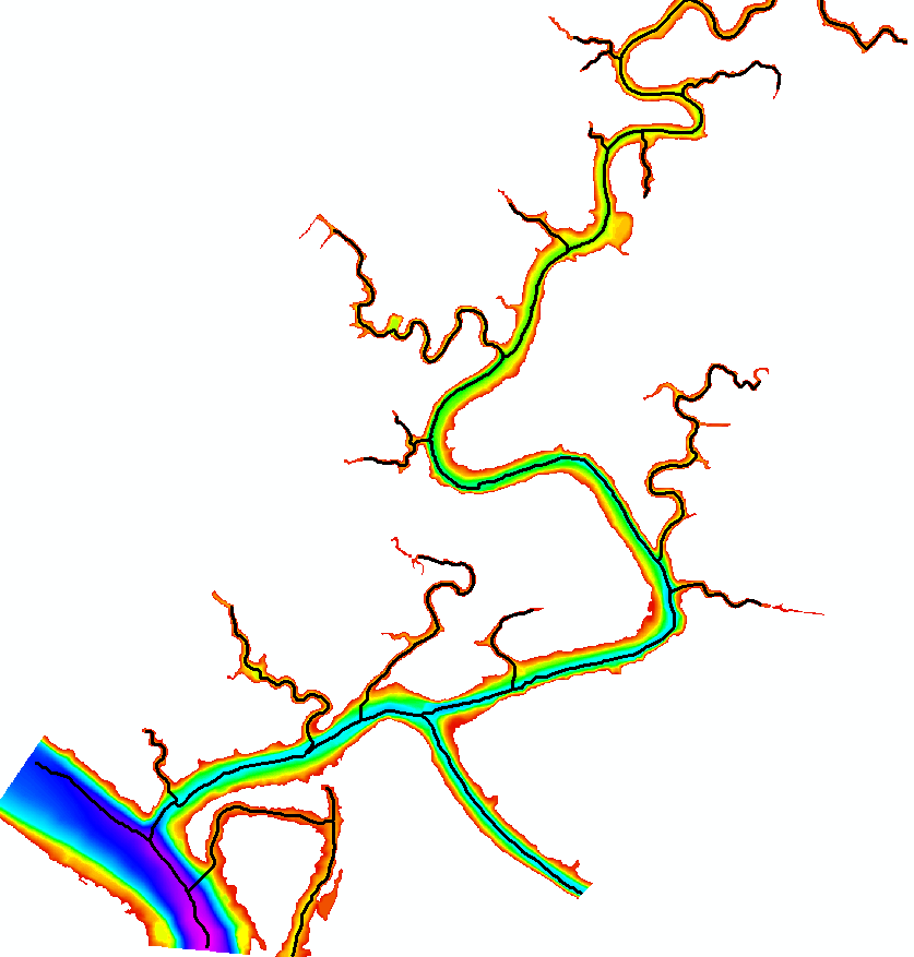
I'm using the Cost Path tool in ArcGIS Desktop 10.3 to draw thalwegs (line of lowest elevation) on a channel network DEM, but running into some problems. In the most simplified case, the raw DEM is used as the cost distance, and the results of Flow Direction are used as the back link (as suggested by ESRI here), which works. The example below shows the output Cost Path over the Flow Direction, with the destinations drawn as polygons. flow direction
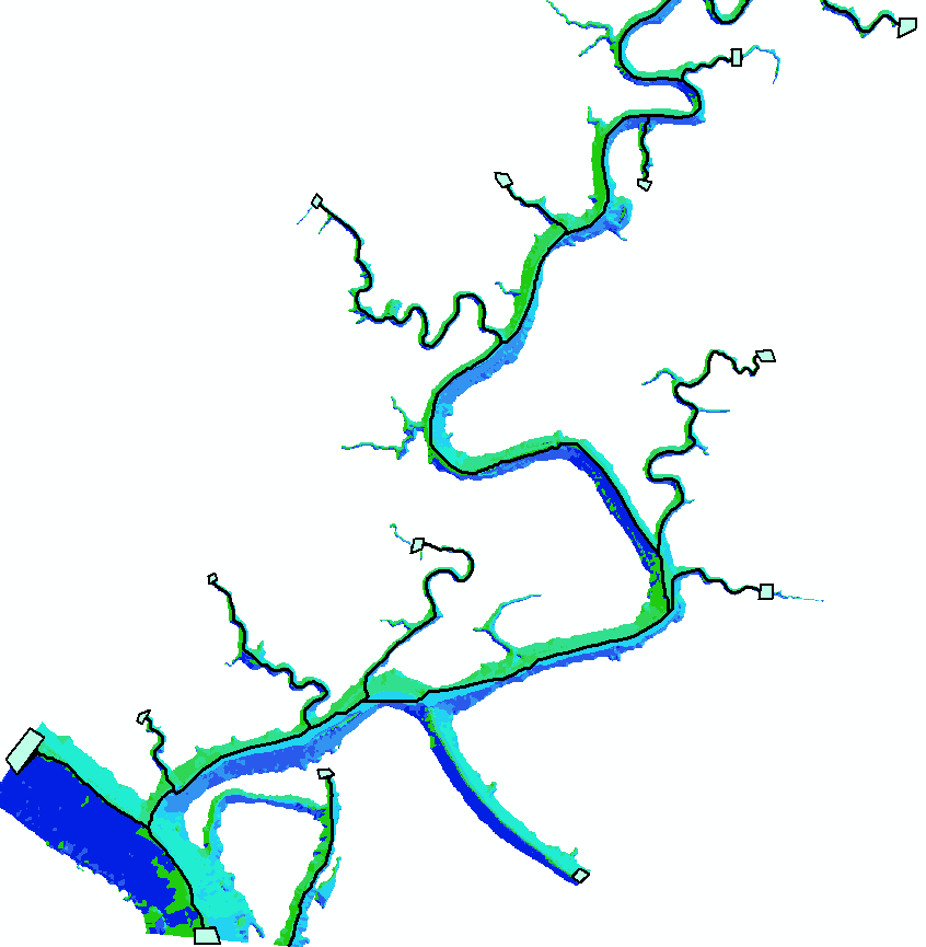
Unfortunately, this is a bit over-simplified, mainly because flow direction requires a Fill operation, and so discards pools in the raster and allows the cost path to "cut corners". I created a weighted raster to account for both slope and proximity to deeper areas, and Cost Distance works fine with this and produces a back link raster which looks good. But running Cost Path with the new cost distance and cost back links simply fills the destination polygons, with no connections drawn between them. For example, here is the weighted raster with the output cost path: weighted raster
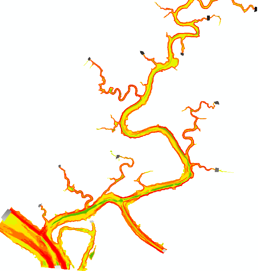
As you can see, the destinations themselves are weighted (as usual), but no path is drawn between them. The strange thing is, any Cost Path I run with Flow Direction as the back link always works, but it also gives me the same output path regardless of the cost raster used. But any time I use the back link produced by other tools, it fails to draw a path.

Some things that I have tried that did not solve this:

  • ensuring geographic projection, processing extent, snap raster, and cell size are identical
  • reclassing the Back Link to the same scale as Flow Direction (1, 2, 4, 8 .. 128)
  • running Cost Back Link separately from Cost Direction
  • using Path Distance instead of Cost Distance or Path Distance Back Link instead of Cost Back Link
  • trying the process on a smaller raster (the original is already only 1421 x 1619)
  • trying Cost Path between two destinations only
  • redrawing the destination polygons so they are fully within the raster bounds

None of these things have worked.

Any ideas?

I'm also aware of a similar function in the River Bathymetry Toolkit Add-In, but that only works in 10.2.

===========================================

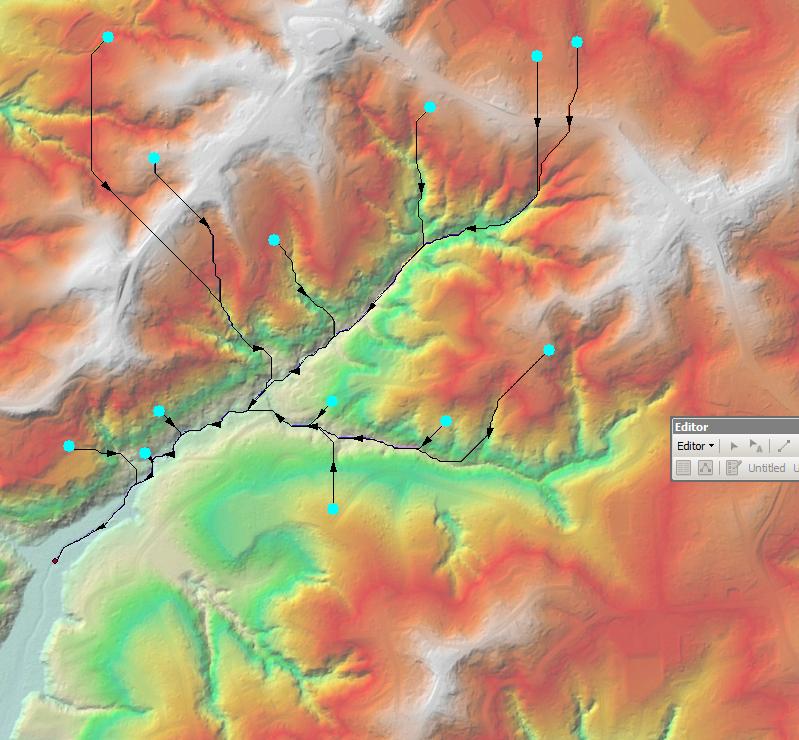
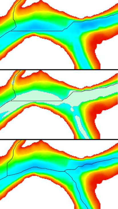
Here's some clarification on why using flow direction as the back link fails for my needs. This is based on a high-resolution (1 m) bathymetry DEM from sonar data. The top panel in the image below show the results of simple flow direction in a cost path overlaid on the DEM. Several corners are cut to produce the straightest path by excluding areas over pools. In order for flow direction to work, Fill must first be run, which effectively sets all pools and large swaths of the bottom to a constant elevation. The areas filled by this operation are illustrated in the second panel. The third panel demonstrates the final method I settled on, use of slope as the cost surface, and the line is clearly a better representation of the thalweg here. enter image description here
Here's the final output: enter image description here

1
  • Did you by chance mix up source (lowest point, used to calculate cost distance and backlink) and destination (points up hill, used as input for costpath). I got good results with this workflow, Fill - Flow Direction - Flow Accumulation - Cost Path (Flow Direction as Backlink, Accumulation as Cost Distance and Points as Destination).
    – EikeMike
    Commented Apr 21, 2017 at 8:42

1 Answer 1

2

I strongly believe that Fill DEM & Flow Direction is the best to achieve your goal nevertheless I did:

arcpy.gp.CostBackLink_sa("POINTS", "DEM", "C:/JOBS/SCRATCH/blink")
arcpy.gp.CostPath_sa("POINTS", "blink", "blink", "C:/JOBS/SCRATCH/paths", "EACH_CELL", "OID")
arcpy.gp.RasterCalculator_sa('Int(Power(2,"blink"-1))', "C:/JOBS/SCRATCH/flowdir")
arcpy.gp.StreamToFeature_sa("paths", "flowdir", "C:/JOBS/SCRATCH/talvegs.shp", "SIMPLIFY")

I.e. used DEM as cost surface: enter image description here

Perhaps converting back link to flow direction went wrong

8
  • If you add a "frame" of with 0.0 height to your DEM before analysis and place your lowest point in this area of 0.0 height, you prevent your costpath from going uphill to get to this point. The costpath will go downhill to the "frame" first and than go with no "costs" to the lowest point.
    – EikeMike
    Commented Apr 21, 2017 at 14:49
  • @EikeMike Agree. However the point I tried to make is: if you have backlink raster you shoul be able to produce paths. This is where Thomas909 stucked
    – FelixIP
    Commented Apr 21, 2017 at 16:34
  • I added some images to the original question explaining why Flow Direction is unsuitable for my raster. For rasters with grid size >= 10 m Fill and Flow Direction are probably best, but for the 1-m rasters I'm using (for hydrodynamic modeling), Fill destroys too much detail. However, I accepted your answer, as your comments along with EikeMike's helped me realize I was using Cost Path and Cost Distance incorrectly -- I didn't interpolate elevations for the destinations, and I didn't select "from" and "to" points.
    – Thomas909
    Commented Apr 24, 2017 at 20:26
  • 1
    Here's the final process that worked well for my needs, starting with a base bathymetric DEM and a set of points for all desired thalweg branches): Slope > Interpolate Shape (points on slope raster) > select exit point all flows will accumulate towards > Path Distance (cost raster = slope, surface raster = base DEM, no horizontal or vertical factors) > reverse selection so all points but lowest are highlighted > Cost Path > Raster to Polyline (min dangle = 4 m) > Simplify Line (BEND_SIMPLIFY, 6 m). This still requires some manual inspection at the end but can mostly be automated.
    – Thomas909
    Commented Apr 24, 2017 at 20:36
  • 1
    My ignorance with these tools is probably showing :) I did it that way because I thought the set of destination points had to have z-values assigned from the cost raster, which in this case was slope. Maybe interpolating from the actual DEM would also work, if that's what you mean. Not interpolating the points at all didn't work (at least in 10.3) --- they were all treated as destinations by Path Distance no matter which was selected.
    – Thomas909
    Commented Apr 25, 2017 at 18:54

Your Answer

By clicking “Post Your Answer”, you agree to our terms of service and acknowledge you have read our privacy policy.

Not the answer you're looking for? Browse other questions tagged or ask your own question.