1

I want to create straight lines based on the points. I used function "Points to Line" which accomplish the task only when the points are sequentially ordered. If they are not ordered, then it creates a zig zag lines (I have included the figures for illustration - Line 2). I have hundreds of lines, and manually editing is not an ideal solution.

How can one create a straight line without manually editing the lines?

I believe one has to take into account of the orientation and the position of the points to address this problem.
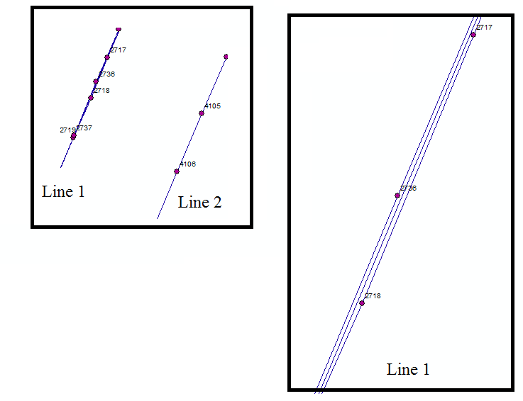
enter image description here

enter image description here[![enter image description here][3]][3]

I also tried running the EMST (Euclidean minimum spanning tree) function in the spanning tree tool. I could connect several lines in the same direction by using "Unsplit Line", but don't know what to do with the lines that connect parallel lines. These are unnecessary lines.

10
  • Could you add more info about how you run the tool? For example what do you use for Line Field and Sort Field?
    – Bera
    Commented Aug 31, 2017 at 18:01
  • For Line Field, I used the field that indicates where those points relate to (e.g., Line 1 or Line 2), and for the sort field, I used FID that indicates the ordering of the points. I also tried not selecting anything for these inputs (since these are optional), and the results came same. It seems like it selects FID as default, and I think this is the problem. Since it looks for FID and the points are not arranged as FID, it creates line between points (e.g., 2717, 2718, 2719 and then goes to find 2736 and 2737, thus making the zigzag lines. Commented Aug 31, 2017 at 18:23
  • Ok so for example the value in the Line Field is the same all points which become Line 1?
    – Bera
    Commented Aug 31, 2017 at 18:26
  • Yes. There is no unique identifier for those points . Commented Aug 31, 2017 at 18:29
  • 1
    Compute minimum spanning tree of these points
    – FelixIP
    Commented Aug 31, 2017 at 18:31

1 Answer 1

1

For this task, you'll want to create a dictionary of line numbers as the dictionary's key and point XYs as their value. Then create your new line feature class with the same spatial reference as your point feature class. Iterate through your dictionary, sort your XYs, and then create a polyline geometry object from your sorted points.

This method assumes that all points that should be connected in a single line have a shared ID value.

Given:

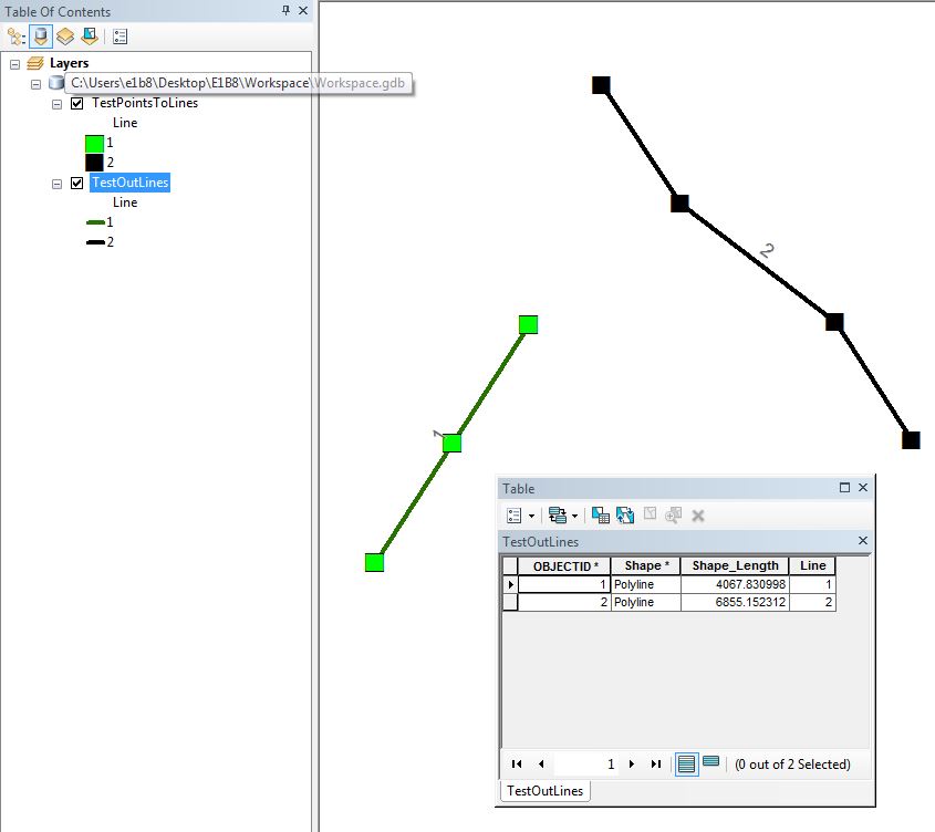
enter image description here

Try this script:

import os
import arcpy

#point feature class
pntFc = r"C:\Path\To\PntFc"
#id field
idFld = "Line"
#line feature class
lineFc = r"Path\To\Output\LineFc"

#create point dictionary
di = {}
with arcpy.da.SearchCursor (pntFc, [idFld, "SHAPE@XY"]) as curs:
     for line, xy in curs:
         try: di [line] += [xy]
         except KeyError: di [line] = [xy]

#create new line feature class
sr = arcpy.Describe (pntFc).spatialReference
linePath, lineName = os.path.split (lineFc)
arcpy.CreateFeatureclass_management (linePath, lineName, "POLYLINE", spatial_reference = sr)

#add line ID field to line feature class
fldType = [f.type for f in arcpy.ListFields (pntFc) if f.name == idFld][0]
arcpy.AddField_management (lineFc, idFld, fldType)

#insert cursor
with arcpy.da.InsertCursor (lineFc, [idFld, "SHAPE@"]) as iCurs:
    #iterate dictionary
    for lineId in di:
        #get point xys
        points = di [lineId]
        #create array
        array = arcpy.Array ()
        for x, y in sorted (points):
            array.add (arcpy.Point (x, y))
        #create geometry
        geom = arcpy.Geometry ("polyline", array, sr)
        #insert row
        row = (lineId, geom)
        iCurs.insertRow (row)

Result:

enter image description here

2
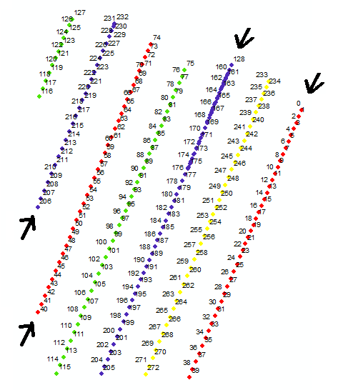
  • I found the issue that was resulting in problem. Although the points fall into certain line groups, they were running in two different directions at a certain distance. I guess there is a need to differentiate between two red lines that are running in opposite directions, and assign them in two groups rather than treating one. This will solve the problem. But, since there are several lines, it is burdensome to manually detect them, and assign them. Is there a way to automatically achieve this? Commented Aug 31, 2017 at 22:04
  • Emil - the program is not working - meaning that it creates zig zag lines. Actually, The points are orientated in such a way that it starts from x location in y direction, and continues in opposite direction at certain distance. I need to create smooth lines that stops right before taking turn. "Points to Line" does a decent job except at corner and when the points are order randomly. Tried sorting options before running the program, but its not helping. Any idea? I can send you the file if it helps to understand the situation here. Commented Sep 1, 2017 at 16:19

Your Answer

By clicking “Post Your Answer”, you agree to our terms of service and acknowledge you have read our privacy policy.

Not the answer you're looking for? Browse other questions tagged or ask your own question.