2

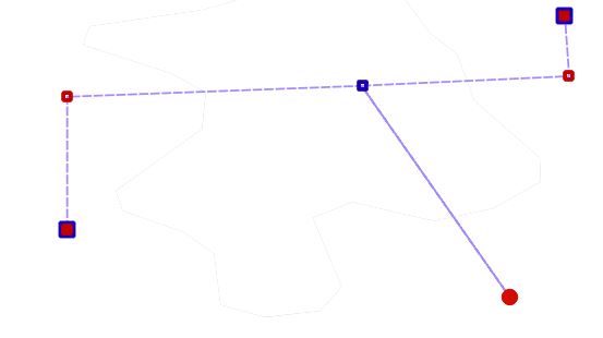
Attached shows a rough drawn image of a pipeline track. I need to measure the pipeline track from one end to the other, e.g from the red and blue square to the other red and blue square, e.g from the blue small square to the red circle.

The issue I am facing is that I have 100's of pipeline tracks to measure. I know using the distance to hubtool will give me a length but not follow the shape of the pipeline, rather will give me a distance in a straight line.

I have also used the measure tool. This tool works but it will take forever to measure 100's of pipeline tracks.

Is there another way which can accurately and efficiently measure the distances? Is that this drawing has no coordinates:

3 Answers 3

3

If i understand your question correctly and those lines are two separate objects in attribute table simple $length expression in field calculator should do the trick.

Edit:

Great answer by CSK below.

I've asked about blueprint format because i had same issues with sewer drawings few years before. Back then I came up with two partial sollutions.

1) Some drawings could be converted with inkscape program to vector format and than georeferenced in QGIS with Vector Bender plugin. After manually deleting artifacts job was done.

2) Other drawings that were too complex (too much artifacts after conversion to delete) or coudn't be converted were georeferenced in QGIS as background. After that I manually draw all the lines.

NOTE: Don't know if its still issue in new versions of QGIS but to get accurate lengths i had to use CRS that had metric format units.

2
  • The information I am working from is an actual blueprint drawing, where there is no attribute table available. it is an image therfore QGIS cannot distingush between any of the items.
    – Louis Tate
    Commented Jul 26, 2019 at 12:35
  • What format is blueprint drawing?
    – sitcaf
    Commented Jul 26, 2019 at 13:40
2

The problem is that your pipeline diagram is a raster image rather than a vector. A human being can easily look at that image and see lines and points, but a computer can't. QGIS doesn't know where the lines and points are, so it doesn't know where you want to measure from and to.

In order to use QGIS to measure the lines, you'll need to convert them into a vector format.

  • Create a new line vector layer in whatever format you want, in an equidistant or local CRS. Use the Add feature button to draw a line feature along each pipeline.
  • Or you could experiment with the GDAL Raster conversion tool Polygonize (raster to vector), but I think it will end up being more work that it's worth to get a clean result.

Once all the pipelines are converted into vector format, use the Field Calculator to add the line length to the attribute table using the $length function. You can then see the length of a given section of pipeline

  • in the attribute table,
  • by clicking on a pipeline using the Identify button,
  • or display all the length values on the map by using the new Length attribute as a label field
0

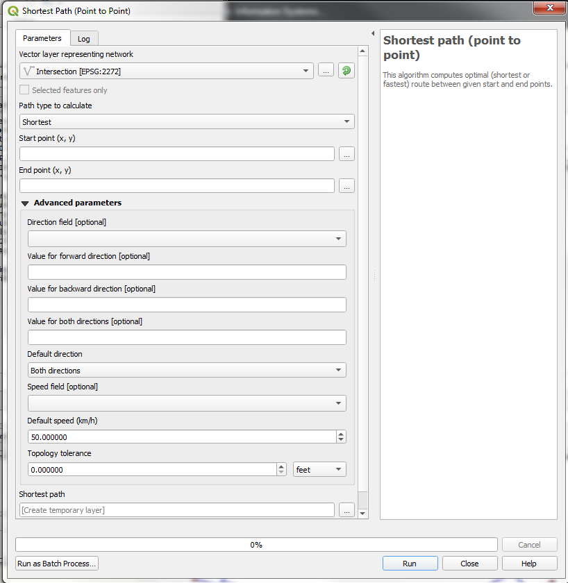
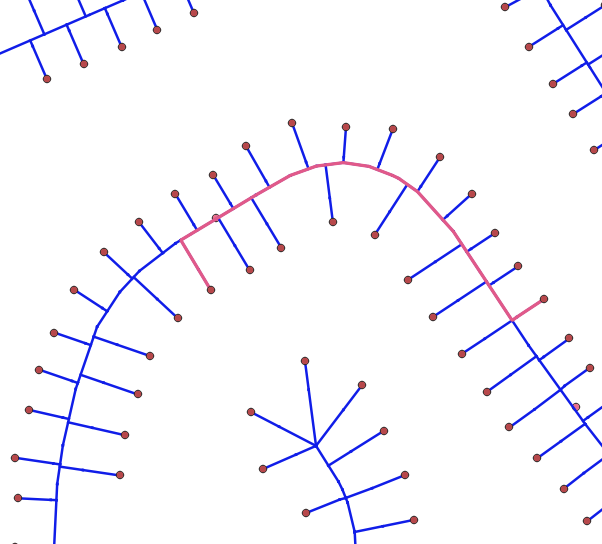
You should be able to use the Shortest Path (Point to Point) located in the processing toolbox. Before running the tool, make sure your lines are separate segments between each intersection ( I used the split lines with lines tool for this part). The pinkish line shown below is the result received. enter image description here shortest path screen

Your Answer

By clicking “Post Your Answer”, you agree to our terms of service and acknowledge you have read our privacy policy.

Not the answer you're looking for? Browse other questions tagged or ask your own question.