5

I combined a set of polygons on the first instance of Geometry generator using something like this:

buffer(buffer(collect( $geometry, concat("MZNA","REGLABEL")), 0.1), -0.1)

Buffers are meant to join poligons with a little separation. Thing is, after that I defined marker lines to simulate measurement, but in the case of multipart polygons, I get random measures floating between the different 'islands'. So I want to separate them before measuring, but I dont know how...

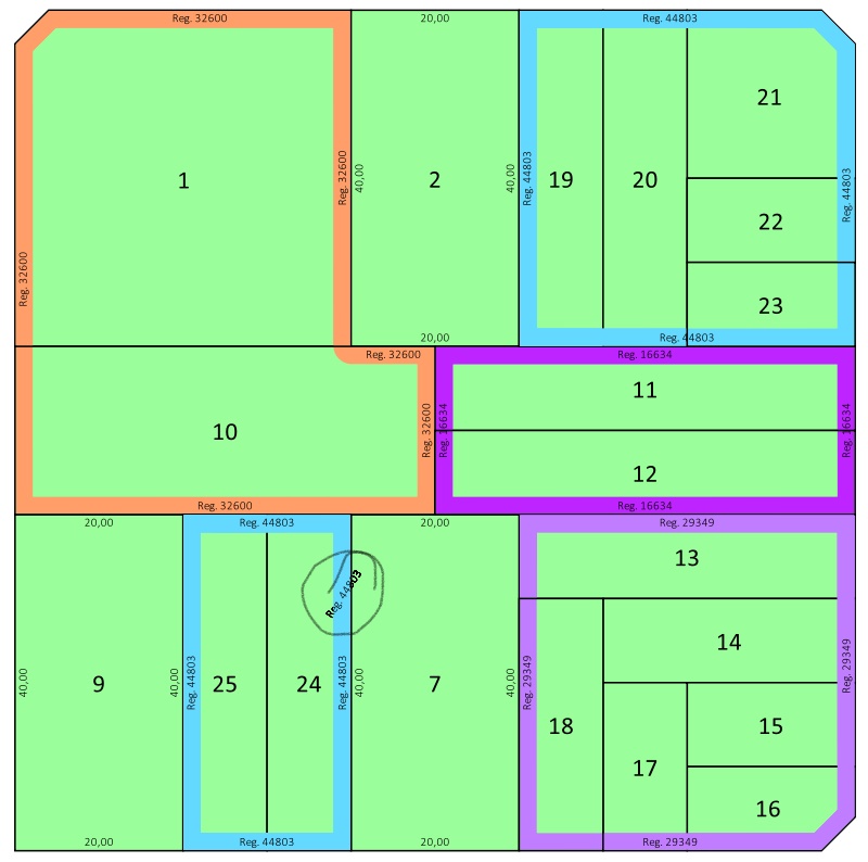
EDIT: What im trying to avoid is this:

Im using the approach shownin QGIS How to label individual sides of polygon by @she_weeds. My problem is, as shown in the pic, after collecting and buffering, I get some multipolygons and those ones gets an extra text floating between the polygon parts. Is there a way to avoid it without dissolving the generated geometry?

Im not experienced enough to know if its possible (started using QGis 2 weeks ago), but i thought some options:

  • Dissolve polygons instead of collecting them, using a python function. Didnt know how to call dissolve from the function editor, didn't even know if it was possible.
  • Apply a filter to the collect statement.
  • When generating lines from points, or text from those lines, somehow test the points to condition the generation of lines.
  • When generating points from nodes, test multipart polygons and generate different sets of points. Managed to successfully test that but didnt manage to create more than one set of points.
1
  • That might not be possible in the geometry generator. collect is one of the aggregate functions. There's no "dis-aggregate" category of functions. There are the @geometry_part_num and @geometry_part_count variables, but I'm not sure how to use them for that.
    – csk
    Commented Sep 9, 2019 at 17:49

1 Answer 1

5

The main problem I see there is that the collect() function creates a part for each original feature, that is: it returns a 7-parts feature for the collection of plots (parcelas) 19 to 25.

The trick of making a buffer generates a false union of the parts: unites them in an attempt to generate valid geometries, because a feature with parts that partially overlap implies an invalid geometry. I don't think we can trust that after the buffer the geometries will always be merged and valid.

In addition, there are still parts for groups that do not overlap. Which brought you here.


I don't know how to cast single-part geometries dynamically from an expression.

So my proposal is that you create a virtual layer with the single-part geometries, all valid and merged. And that you use that layer to label the sides of the groups.

Since the problem of dumping geometries in a virtual layer is not completely solved I will focus on that problem, seeing that you have already solved how to label it.

You should create a virtual layer with the following SQL query:

WITH RECURSIVE parts AS (
  SELECT t.fid, t.total, 1 AS part
  FROM totals AS t
  UNION ALL
  SELECT t.fid, t.total, part + 1 AS part
  FROM totals AS t 
  INNER JOIN parts AS p ON t.fid = p.fid AND p.part < t.total
  ),

totals AS (
  SELECT fid, NumGeometries( geom) AS total
  FROM merged
  ),

merged AS (
  SELECT fid , MZNA, REGLABEL, ST_Buffer(ST_Union(ST_Buffer(geometry, 0.1)), -0.1) AS geom
  FROM plots
  GROUP BY MZNA, REGLABEL
  )

--SELECT * from merged;
--SELECT * from totals;
--SELECT * from parts;
-- to debug, comment on the following lines and uncomment the previous SELECT clause of your interest.
SELECT p.fid, m.MZNA, m.REGLABEL, p.part, GeometryN( m.geom, p.part) as geom
FROM parts AS p
INNER JOIN merged AS m ON p.fid = m.fid;  

I am assuming that the source layer is called plots and that all its features have a unique fid value.


The virtual layer has been saved in the project, it is not a separate file. It has the advantage that any modification in the original layer should be immediately reflected in the virtual layer, each time those changes are saved and the canvas re-freshed / re-rendered.

About the query:

  • I came to it as a first solution to the problem of dumping geometries in the environment of a virtual layer, of which I did not find a previous solution. (It can surely be improved.)

  • The merged Common Table Expression (CTE) performs the union of the original geometries, grouped by the values of the MZNA and REGLABEL fields. A buffer and anti-buffer is performed as a precision threshold of the digitization of the plots. This table returns fields of interest and (multi-parts if distant) merged geometries.

  • The totals CTE just returns the fid and total (number of parts) fields.

  • The parts RECURSIVE CTE performs an iterative addition for each fid of multiple rows, starting with part 1 until part is equal to total.

  • Finally, for each row of the parts CTE, we select the fields from merged and each part of any geometry, following the parts rows. The part value is returned just to debugging purposes.

8
  • WOW nice SQL query! I thougt about using a virtual layer but failed, and ended up writing a process tool to generate a new shapefile and aplying a previous symbol style to it... Im now leaving the office but tomorrow ill try this and comment the result! Thanks a lot!
    – Opazo
    Commented Nov 13, 2019 at 17:56
  • @Opazo You are welcome. I just included the buffer and anti-buffer, as a precision threshold of the digitization of the plots. Also included debugging lines. Some debug tables (totals and parts) don't have geometries and the layer loses its style when that tables are returned, so make sure to save the style in a .qml file before debug. Test with your data, I will be aware of your opinion about the performance of the query. Commented Nov 14, 2019 at 1:26
  • Tryed to do this but had a syntax error... Later I realized that it wont work cause I dont have a fid value... Can this be done for a set of merged layers instead of just 'plots'? Vi en tu perfil que hablas español pero no se si es permitido en esta pagina jeje
    – Opazo
    Commented Nov 14, 2019 at 17:06
  • We prefer English, so we understand ourselves from anywhere in the world. If you included in your question a summary or an example with the data model (what are the layers and their fields called), I could adapt the query. Commented Nov 14, 2019 at 20:28
  • Hello Gabriel, I came back to work and tryed to implement your SQL query. It did not throw any error and the attribute table seems to be OK but im not being able to get a visualization of the polygons... Am I doing anything wrong? I just copied and pasted the code in the virtual layer creator... I have only QGis 3.10 now
    – Opazo
    Commented Jan 3, 2020 at 11:15

Your Answer

By clicking “Post Your Answer”, you agree to our terms of service and acknowledge you have read our privacy policy.

Not the answer you're looking for? Browse other questions tagged or ask your own question.