6

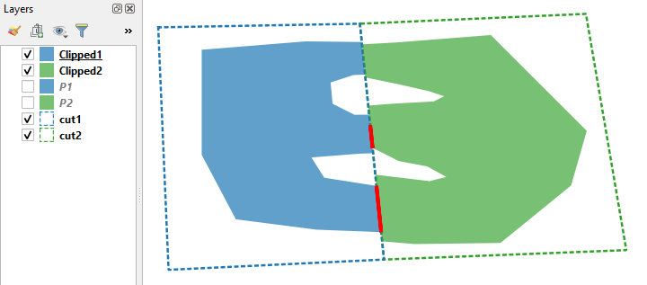
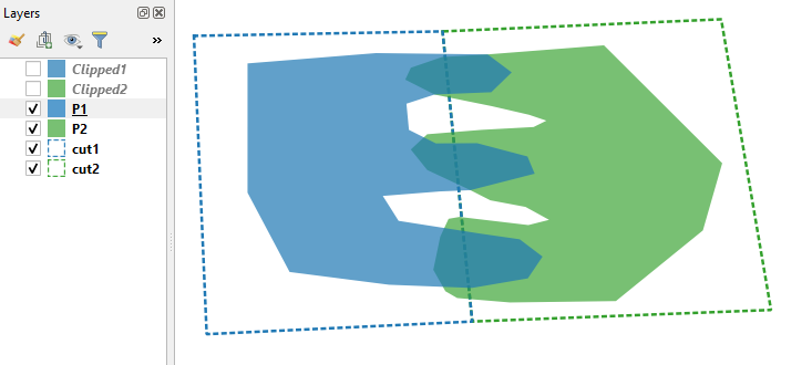
I have two layers in QGIS with intersecting polygons (blue "P1" and green "P2"). I want to clip them with adjacent polygons tiles (dotted line - blue "cut1" and green "cut2"). enter image description here

Why the result clipped polygons ("Clipped1", "Clipped2") still overlap? The red line is the result of the topology checker tool in QGIS with the rule "Clipped1 must not overlap Clipped2". enter image description here

The checker is indeed right because when I try to collect geometries in "Clipped1" and "Clipped2" to one layer and one feature, the result is invalid self-overlapping multipolygon geometry.

This is just an example. I am doing this because I have vectorized land use data from overlapping raster tiles. I want to clip these data to exact adjacent boundaries (specified in adjacent polygons tiles like "cut1"). I do not want the result data to overlap.

The example QGIS project and data are shared here:

5
  • Which QGIS version do you use?
    – Nil
    Commented Jan 3, 2021 at 15:04
  • 3
    The reason may be due to limited accuracy of floating point computing. If this is the case the overlaps are typically at micrometer-nanometer scale.
    – user30184
    Commented Jan 3, 2021 at 15:04
  • I use QGIS version 3.14.16-Pi (gdal 3.0.4). But the same problem is present when I use GDAL version 3.2.0 from command line (command ogr2ogr with -clipsrc parameter). Commented Jan 3, 2021 at 15:39
  • Interesting! Although all of your input data appears to be correctly formed, the clip creates two very small sliver polygons derived from P1 – P2 overlaps, which the topology check correctly identifies. When I project your data to shapefiles with EPGS: 32634 (UTM 34N, appropriate for your study area) and calculate the area of the two sliver polygons in square meters, the results are 1.2215721767461218e-09 and 4.316348167776596e-09. However, when I replicate my experiment with Arc Desktop, no sliver polygons are created. Perhaps a QGIS clip bug?
    – Stu Smith
    Commented Jan 3, 2021 at 19:33
  • 1
    This issue is also interesting because the topological problem only occurs in the southern half of the study area. I checked to see if that could be related to any pseudo-nodes along the clip boundary, either in the input or output layers, but there were none. I am still puzzled by this issue!
    – Stu Smith
    Commented Jan 3, 2021 at 19:34

2 Answers 2

4

I can't say how to correct the topology automatically but these images should show what happens.

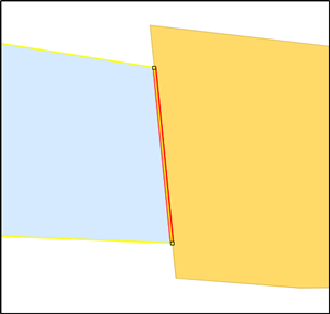
These are the vertices of the left side polygon (clipped1) and the location of the overlap.

Left side polygon

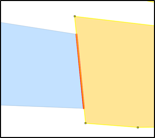
These are the vertices of the right side polygon (clipped2) and the location of the overlap.

Right side polygon

The overlap is in the middle of the segment of the right side polygon. The right side polygon does not have real vertices there. It would be easy to fix the topology by adding manually two vertices into the right side polygon and snap them to the vertices of the left side polygon. However, in your workflow this should happen automatically and I do not know how to do it. OpenJUMP does have a tool for that purpose, even it requires that the polygons that must be adjusted are all on the same layer.

enter image description here

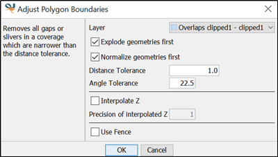
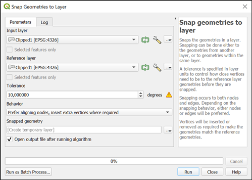
The QGIS tool "Snap Geometries To Layer" looks promising to me but I have not used it myself (image captured with the default values, 10 degrees tolerance is of course wrong, it should rather correspond to something like 0.1 millimeters).

enter image description here

I would not say that there is not a bug in the clip tool at least when it is used for clipping separate layers. When the tool is clipping the right side geometry (clipped2 in your dataset) it cannot know that the new vertices should be added and snapped from the left side geometry (clipped1). And because of inaccuracies in floating point computing it may be impossible to avoid overlaps or gaps if polygons do not use exactly same vertices on the common boundary.

ArcGIS desktop may be applying a tolerance when it compares the geometries.

1
  • 1
    The paragraph after the Snap Geometries image is a good explanation for why the clip tool can produce topology errors. See ian-ko.com/resources/Topology_Problems_2.htm for more on this. One solution is to merge the clipped polygons and run a v.clean. They can be split apart afterwards
    – John
    Commented Jan 5, 2021 at 20:52
1

So, your raw data in text format is shown below:


    P1

MULTIPOLYGON(((
20.0857554080356 49.1905790194619,
20.0887585780746 49.1908207752517,
20.0913701395045 49.1907900830797,
20.0919317359928 49.1903683481409,
20.0914538692795 **49.189904400853**,
20.0901285682587 **49.189850570172**,
20.0894706448357 49.1896357656678,
20.0895286338877 49.1890226017499,
20.0901585196318 49.1887062364486,
20.0911232107661 49.1887112266666,
20.0923003889932 49.1883999801812,
20.0924689512343 49.1879964788981,
20.0909664123542 49.1876106012218,
20.0902648144706 **49.187582101503**,
20.0889184239773 49.1874761042477,
20.0892866229602 49.1868926429941,
20.0911929486599 49.1865939365032,
20.0921185085797 49.1864605487381,
20.0926524563312 49.1860547869236,
20.0923093739486 49.1855450205898,
20.0910002892154 49.1853208756588,
20.0890629836294 49.1853960467621,
20.0867393344223 49.1856948489684,
20.0857549014584 49.1875526825485,
20.0857554080356 49.1905790194619)))

    P2

MULTIPOLYGON(((
20.0940891015883 49.1910030596365,
20.0913701395045 49.1907900830797,
20.0903062930032 49.1907297755622,
20.0895736190903 49.1904777401952,
20.0894434734106 49.1901988882585,
20.0901285682587 **49.189850570172**,
20.0914584759702 49.1895797307578,
20.0923385575252 49.1893761011687,
20.0927428359831 49.1892386365323,
20.0924438824452 49.1890897163163,
20.0912241556408 49.1890230861748,
20.0899556817257 49.1889202672104,
20.0895721247598 49.1885627287066,
20.0899566457058 49.1880825153734,
20.0909664123542 49.1876106012218,
20.0914323110225 49.1873730578066,
20.0922555546796 49.1872184151039,
**20.092805836504** 49.1869159021594,
20.0923217841585 49.1867936607209,
20.0907125632431 49.1869847702754,
20.0904559362005 49.1869401500279,
20.0902607247448 49.1865218730033,
20.0900993371189 49.1857459160426,
20.0903815062651 49.1852444458059,
20.0906574479955 49.1850846778018,
20.0918931767317 49.1849809902124,
20.0943680763247 49.1850130843569,
20.0964027568943 49.1866686445626,
20.0968540580765 49.1882428430747,
20.0940891015883 49.1910030596365)))

    cut1

MULTIPOLYGON(((
20.0845012519789 49.1912243404059,
20.0847997794355 49.1842387979217,
**20.091009397156** 49.1845347476421,
**20.090314889771** 49.1913285461957,
20.0845012519789 49.1912243404059)))

    cut2

POLYGON((
20.090314889771 49.1913285461957,
**20.091009397156** 49.1845347476421,
20.0979946930168 49.1848060000892,
20.0968304359361 49.1916124260995,
**20.090314889771** 49.1913285461957))

As a consequence, my version of the answer is as follows:

your raw data P1 and P2 and blades cut1 and cut2 have different precision, namely 12 and 13 digits after the decimal point, and that is why you have "artifacts" when geo-processing them further,

like so-and-so...
1
  • Is there a possibility to control the precision in QGIS or GDAL command line tools, like ogr2ogr? For example set the tolerance for spatial operations, or something similar... Commented Jan 5, 2021 at 15:48

Your Answer

By clicking “Post Your Answer”, you agree to our terms of service and acknowledge you have read our privacy policy.

Not the answer you're looking for? Browse other questions tagged or ask your own question.