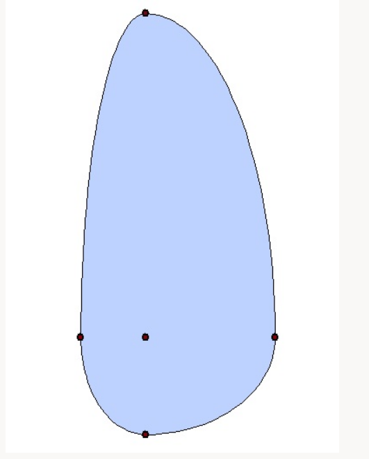
You can use this expression to create such a polygon:
smooth (
    make_polygon(
        make_line (
            project ($geometry, 10, radians(0)),
            project ($geometry, 15, radians(90)),
            project ($geometry, 5, radians(180)),
            project ($geometry, 20, radians(270))
        )
    ),
    10
)
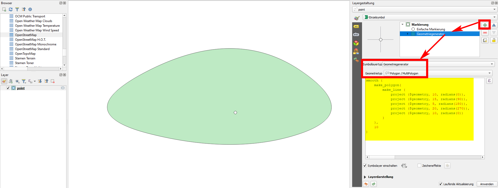
Add a symbol layer of the type Geometry generator, set it to Geomtry type Polygon and paste the expression. Change the values of the buffer distance (here: 10, 15, 5, 20) manually. In between you could add additional points if you like with the same syntax: project ($geometry, [distance], radians([degrees])): simply replace [distance] with a value for distance and [degrees] with the azimuth (angle from 0 to 360, measured clockwise starting from north).
This method is for visualization purpose only. If you want to create actual geometries however, use Menu processing / Toolbox / Geometry by expression and paste the same expression.
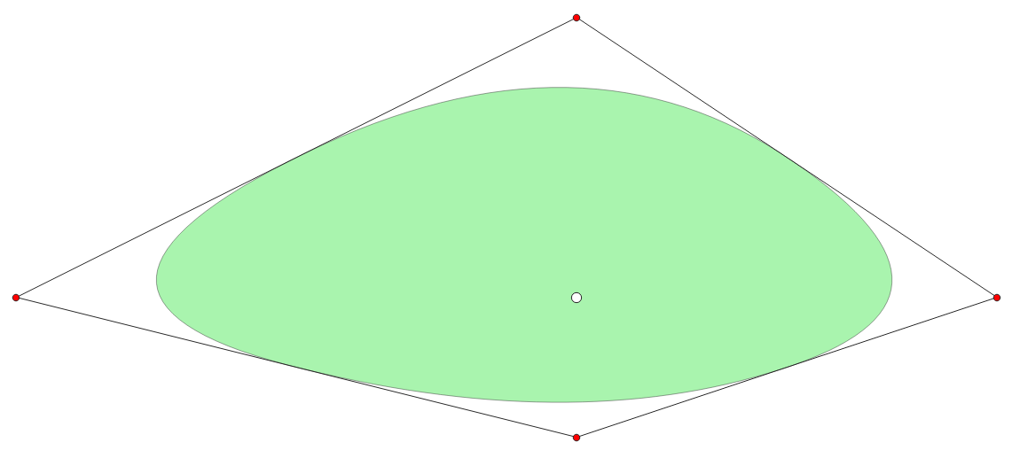
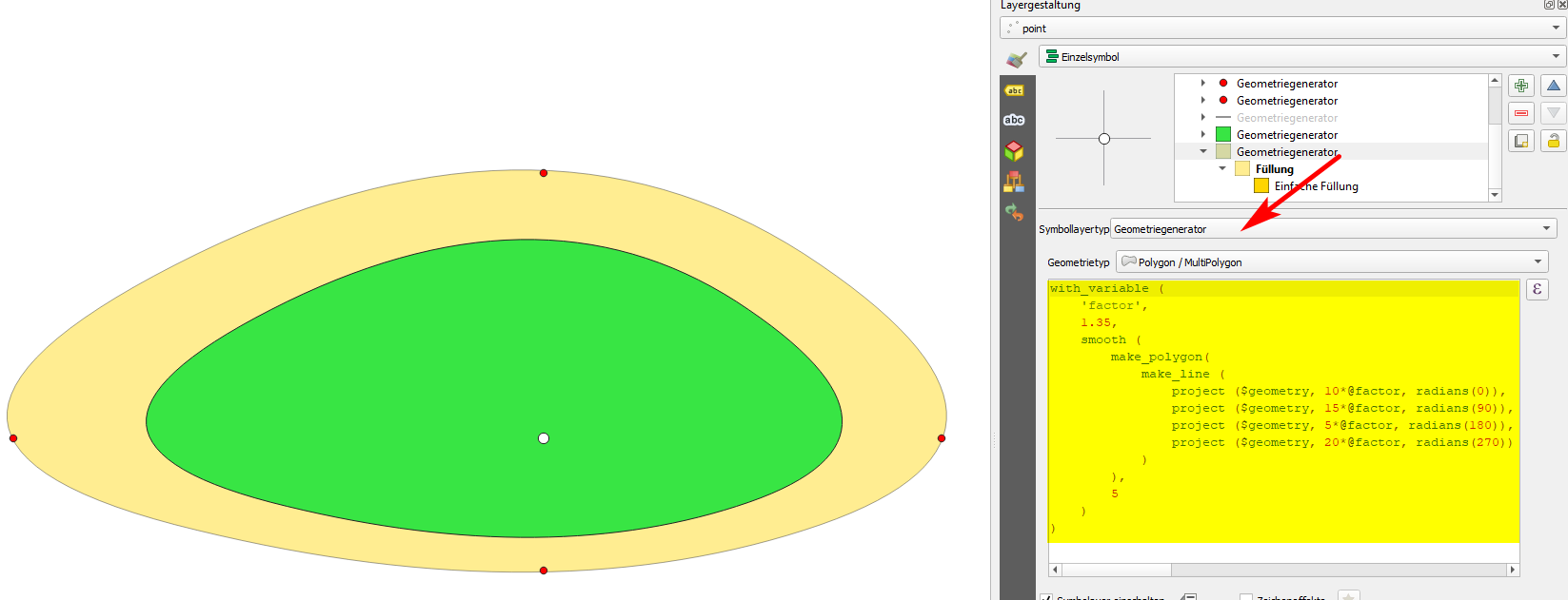
There is a slightly improved version of this solution to get rid of its major drawback: by smoothing the line, it does not pass any longer through the points defined. See on the next screenshot: the red points are those defined by distance and azimuth (lines 4 to 7 in the expression above). The black line connects them (line 3). The function smooth (first and penultimate line) makes this line smoother, so when creating a polygon out of it (line 2), the resulting geometry (green polygon) looks nice, but is much smaller as you would expect because it does not reach the red points any more:
By adding a factor that multiplies the distance, the created polygon gets larger. First use this expression in the geometry generator to see changes in real time and to adapt the value of the factor (line 3 in the following expression, in my case: 1.35) as long as the resulting polygon fits its size as to pass through (or pass nearby) the dots that define the extent of the canopy:
with_variable (
    'factor',
    1.35,
    smooth (
        make_polygon(
            make_line (
                project ($geometry, 10*@factor, radians(0)),
                project ($geometry, 15*@factor, radians(90)),
                project ($geometry, 5*@factor, radians(180)),
                project ($geometry, 20*@factor, radians(270))
            )
        ),
        5
    )
)
The green polygon is the one created in the first solution, the yellow one the one with the second one:
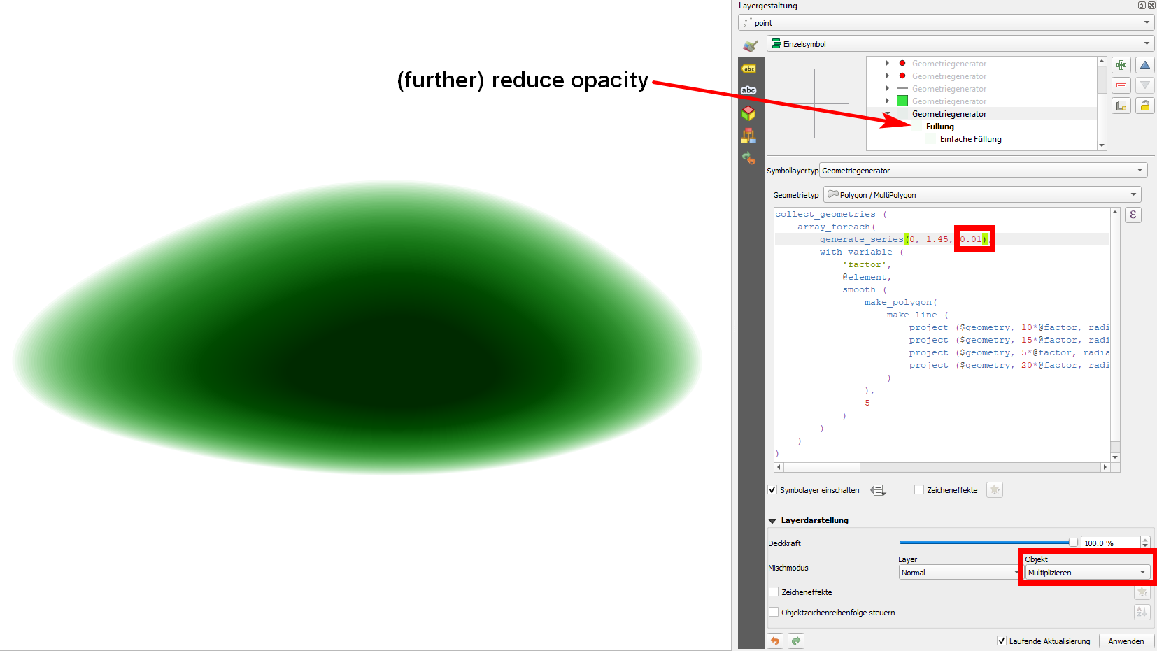
You can now further experiment and create repeated geometries with different distances, using the array_foreach to define an start- and end-distance as well as an interval to draw several different polygons with varying distances. If you than reduce the opacity of the color of the symbol layer, you can simulate nice "blurry" effects (see screenshot below): in the middle, the tree is darker than at its outer boundary:
collect_geometries (
    array_foreach(
        generate_series(0.5, 1.45, 0.05),
        with_variable (
            'factor',
            @element,
            smooth (
                make_polygon(
                    make_line (
                        project ($geometry, 10*@factor, radians(0)),
                        project ($geometry, 15*@factor, radians(90)),
                        project ($geometry, 5*@factor, radians(180)),
                        project ($geometry, 20*@factor, radians(270))
                    )
                ),
                5
            )
        )
    )
)
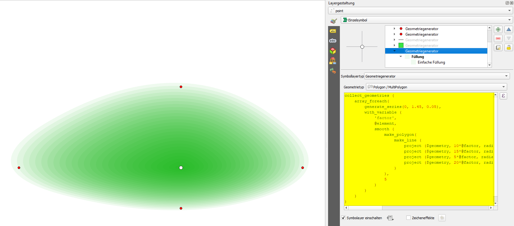
You can further improve this effect by changing the blending mode of the features (see screenshot: I applied multiply), by reducing the interval between the individual polygons (screenshot: reduced to 0.01) and (further) reducing the opacity of the symbol layer's color:
