How would you generate building shadows from building footprints?
I have attribute values for the heights of buildings.
So would preferably like to have the shadows' sizes vary based on that.
The best suggestion I've found using ArcGIS is drop shadows: http://blogs.esri.com/Support/blogs/mappingcenter/archive/2008/10/21/3d-effect-for-a-building-footprints.aspx
-
2ArcMap/Python code for a solution is provided in the continuation at gis.stackexchange.com/questions/19935/….– whuberCommented Feb 10, 2012 at 22:36
-
Can you please provide the script using python for the first example as i need to identify the shade of some shading devices. your response is highly appreciated– user28701Commented Apr 1, 2014 at 11:46
3 Answers
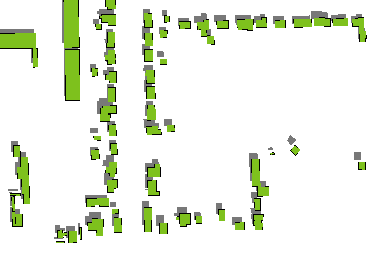
A quick and dirty method is to draw the shadows of the building roofs only, render them in dark gray (preferably semi-transparent if there are any underlying ground layers), and draw the building polygons over them. The roof shadows are obtained by translating the building polygons by the distances determined by the building heights in the direction established by the azimuth and altitude of the light source (considered to be infinitely far away). (A formula for the amount of translation appears below.)

This tends to work ok except for low altitudes or tall buildings (such as skyscrapers): see how the shadows of the taller isolated buildings on the right hand side are separated from the buildings themselves.
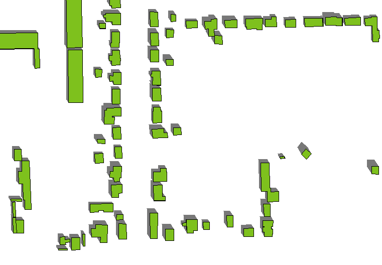
To connect the shadows properly to the buildings, you need to include the shadows of the building walls. This isn't hard to do. The shadow of the wall extending between a point located at P and another point located at Q will be the quadrilateral outlined by {P, Q, Q', P'} where Q' is the shadow of Q and P' is the shadow of P. A polygonal building will be a collection of connected polygons represented by closed sequences of points (P(1), P(2), ..., P(n)). For each such polygon, form the union of the shadows of the edges (P(1), P(2)), (P(2), P(3)), ..., (P(n), P(1)). This is straightforward to do by means of a loop over the edges.
For a light at an azimuth of a degrees (east of north) and an altitude of s degrees (from the horizon), the shadow of a point P with projected coordinates (x,y) and height h (all expressed in the same units, such as meters) is located at P' = (x - hsin(a)/tan(s), y - hcos(a)/tan(s)). You only have to compute sin(a)/tan(s) and cos(a)/tan(s) once for the entire layer, and for each polygon you only have to multiply those factors by the height once to obtain the offsets for each point shadow in the polygon. (The real computational workload is carried by the GIS, not your code, as it forms the unions of all these quadrilaterals.)
Here's an example of the effect. (The azimuth and altitude have changed slightly compared to the first figure, but the building polygons and heights--which vary--are the same as before.)

Appendix
In response to a request, here's the code used to create the second example. Although almost nobody uses this language (Avenue) anymore, it could well serve as pseudocode for creating a solution in your favorite GIS. (Unlike most pseudocode, however, it has been tested by actually running it. :-) It's so simple that no explanation should be needed; just be aware that indexing starts with 0, not 1, and that polygon rings are explicitly closed (the last point in the list coincides with the first point).
' S
' Return the shadow of a shape.

' Field calculator example:
' av.run("S", {[shape], [height], 200, 35})
'======================================================================'
theShape = SELF.Get(0) ' A projected polygon
xHeight = SELF.Get(1)  ' Expressed in the projected units
xAzimuth = SELF.Get(2).AsRadians  ' Any angle (in degrees) east of north
xAltitude = SELF.Get(3).AsRadians ' Angle between 0 and 90 (vertical)
'
' Compute the shadow offsets.
'
xSpread = 1/xAltitude.Tan
x = -xHeight * xSpread * xAzimuth.Sin
y = -xHeight * xSpread * xAzimuth.Cos
xy = x@y
'
' Begin with the original shape.
'
p = theShape.Clone
'
' Adjoin the wall shadows.
'
for each lPts in theShape.AsList   ' Loop over the rings
  for each i in 1..(lPts.Count-1)  ' Loop over edges in this ring
    l = {lPts.Get(i-1), lPts.Get(i), lPts.Get(i)+xy, lPts.Get(i-1)+xy}
    p = p.ReturnUnion(Polygon.Make({l}))
  end
end
return p
' end of script
-
1How do buildings with donut holes look with this algorithm? Does it allow for a non-shadowed area to exist in, say, a courtyard, given azimuth and altitude values that would cause that in real life?– blah238Commented Nov 23, 2011 at 5:15
-
2@Blah Yes. You can see some partial courtyards in my examples, such as the groups of buildings in the lower left corner.– whuberCommented Nov 23, 2011 at 5:30
-
Thanks for the help. I'm just picking this up right now. Any examples of how to implement this? Commented Nov 23, 2011 at 18:27
-
5@Eighty I confess to doing this work with a field calculation in ArcView 3: it's simple, one can write the script faster than it takes to start ArcMap :-), and it executes in almost no time at all. The output shapefile can then be read by ArcMap for rendering if you like.– whuberCommented Nov 23, 2011 at 18:38
-
2I'm looking forward to seeing the Python script someone puts together to make this work in ArcMap! Commented Nov 23, 2011 at 20:24
I don't think what you are talking about (looking for) is going to be a capbability in arcmap (version?)
See this question for probably the limitation you are not wanting.
Utilizing 3d Analyst extension and arcscene you can add light but there are still some limitations.
There is some esri movement on the matter with cityengine.
Scroll down to the shadow accuracy section.
I have previously been associated with lightscape (which has been retired and I am sure lives on inside of 3dsmax).
Now the path would probably be through the engineering visualization product line...
3ds Max
-
Thanks for the outline of my options, Brad. I'm using Arc 10. I don't think I necessarily need light, I just need 2D shapes for the shadow footprint connect the shadow shape from the corners of the building rather than the result produced by a drop shadow. Commented Nov 22, 2011 at 19:15
-
I must have mis-read. I thought to get the shadow by height you would need that generated by a light source. Commented Nov 22, 2011 at 19:34
-
2I think I can vary the size of the shadow shapes just using the attribute values I have for the height of the buildings? My problem seems to be in creating a shadow that's not a drop shadow, but a shadow that actually is connected to the corners of the building footprint. Commented Nov 22, 2011 at 19:46
The 3D Analyst extension has some tools (Skyline and Skyline Barrier) for producing silhouettes and shadow volumes but it's in the context of being projected against a vertical plane as in a skyline, so I'm not sure how or if it could be easily adapted to this case (projecting against a horizontal plane, the ground).
