1

Is there a tool that can convert a point dataset to a polygon based on some known parameters.

We will have

1- x,y

  1. Azimuth

3.Distances in m for a- point in the direction of 2 (the azimuth) (200m), distance 180 degrees from 2 (25m), and distance -90/90 from the point (12m)

So the shapes will be something like this and be based on the point dataset. enter image description here
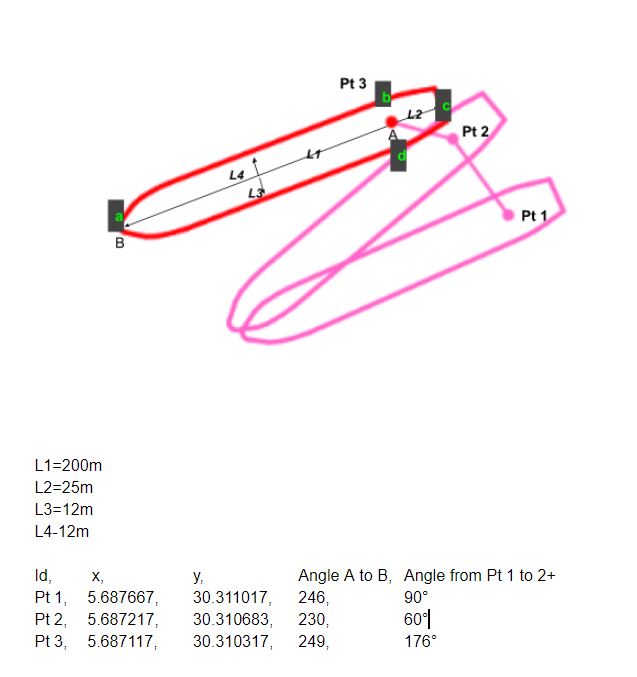
We need to get the x,y for points lowercase a-d and then create a polygon based on these. If this is possible this can then be easily updated to have more points and create a better shape but the key question here is how can we create these points...

Is the only way to do this using spatial maths as in Creating points based on distance and bearing from survey point using QGIS?

Over the last year is there a plugin to achieve this?

Unfortunately, the Azimuth and Distance plugin works based on starting from a point and moving along that, whereas here I have multiple points and fixed dimensions.

The process to build a plugin/model to do this seems to be in http://www.portailsig.org/content/pyqgis-des-geometries-des-vecteurs-de-l-algebre-vectorielle-ou-des-cosinus-directeurs-exempl but I don't want to recreate the 'wheel' if I don't need to...

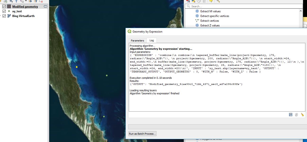
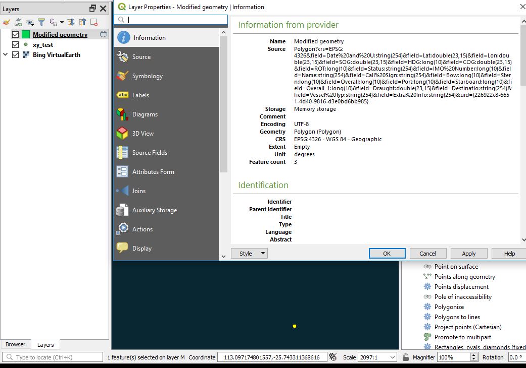
UPDATE Unfortunately, my result with Kazuhito's reply is enter image description here and I get 2019-03-12T04:00:49 WARNING Cannot zoom to selected feature(s) : No extent could be determined. Working in WGS 84. enter image description here
2
  • Could you annotate your picture?
    – Kazuhito
    Commented Mar 11, 2019 at 9:46
  • @Kazuhito I have improved the picture. We do actually have an additional piece of info which is the angle from A to B which is L1. L4/L3 will be +/- 90d of this and L2 is 180d. This gives us the shape we want. The final value is simply the direction from Pt 1 to 2 to 3. This shouldn't be needed to get a result for this question.
    – GeorgeC
    Commented Mar 11, 2019 at 10:23

1 Answer 1

3

Probably you can do this in two steps:

[Step 1] Create a series of points layer (Pt1, Pt2, ...)

[Step 2] Build the polygon at each point geometry from [Step 1].

Let me try to provide an answer for the [Step 2] part... building the ship ... if I can call them ships.

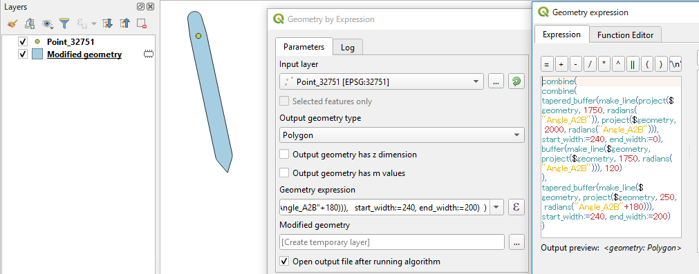
Tool is Geometry by expression in the Processing Toolbox >> Vector geometry.

combine(
 combine(
  tapered_buffer(make_line(project($geometry, 175, radians("Angle_A2B")), 
                           project($geometry, 200, radians("Angle_A2B"))), 
                 start_width:=24, end_width:=0),
  buffer(make_line($geometry, project($geometry, 175, radians("Angle_A2B"))), 12)
  ),
 tapered_buffer(make_line($geometry, project($geometry, 25, radians("Angle_A2B"+180))), 
                start_width:=24, end_width:=20)
)

The above expression combines three parts (bow, body, and stern of the ship).


Details about the above expression:

[The bow] ... ... a tapered buffer (175m~200m from the point A)

tapered_buffer(make_line(project($geometry, 175, radians("Angle_A2B")), 
                           project($geometry, 200, radians("Angle_A2B"))), 
                 start_width:=24, end_width:=0)

[The body] ... ... a 175m long x 2*12m wide buffer (the point A is at the rear end)

buffer(make_line($geometry, project($geometry, 175, radians("Angle_A2B"))), 12)

[The stern] ... ... a tapered buffer (0m~25m toward the opposite side) The tail ends at 20m width. Please adjust as required.

tapered_buffer(make_line($geometry, project($geometry, 25, radians("Angle_A2B"+180))), 
                    start_width:=24, end_width:=20)

Because combine() can take only two geometries, I used it twice to combine three geometries (combine(bow, body) and then with stern).

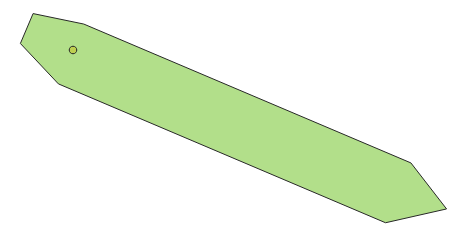
enter image description here

NB - My expression in the picture is scaled by x10 times :)

I did not answer to [Step 1] but project($geometry, distance, azimuth()) will get you what you need.


[Update]

"if the width is 14m on one side and 18m on the other (L3/L4) - how do we change the body calc to deal with this?"

convex_hull(
  combine(
    make_line($geometry, project($geometry, 200, radians("Angle_A2B"))),
  combine(
  combine(
    offset_curve(make_line($geometry, project($geometry, 175, radians("Angle_A2B"))), 14),
    offset_curve(make_line($geometry, project($geometry, 175, radians("Angle_A2B"))), -18))
  ,
  combine(
    offset_curve(make_line($geometry, project($geometry, 25, radians("Angle_A2B"+180))), 7),
    offset_curve(make_line($geometry, project($geometry, 25, radians("Angle_A2B"+180))), -9))
)))

enter image description here

4
  • brilliant - but I can't see any result. There is a table that's created but zoom to layer doesn't show anything. I will update the question with this. Can you send your test data to make sure I am not missing something simple?
    – GeorgeC
    Commented Mar 11, 2019 at 17:25
  • I tried this but get the same result. Will send a test dataset shortly.
    – GeorgeC
    Commented Mar 11, 2019 at 22:05
  • no need -it works now. I just had what you call "Angle_A2B" as "HDG" and off course making sure it was in UTM.
    – GeorgeC
    Commented Mar 11, 2019 at 23:11
  • if the width is 14m on one side and 18m on the other (L3/L4) - how do we change the body calc to deal with this?
    – GeorgeC
    Commented Mar 12, 2019 at 7:13

Your Answer

By clicking “Post Your Answer”, you agree to our terms of service and acknowledge you have read our privacy policy.

Not the answer you're looking for? Browse other questions tagged or ask your own question.