You can use the QGIS plugin LRS for that. It accepts points not lying on the line, so you avoid the first step (snapping points to lines).
This is the workflow:
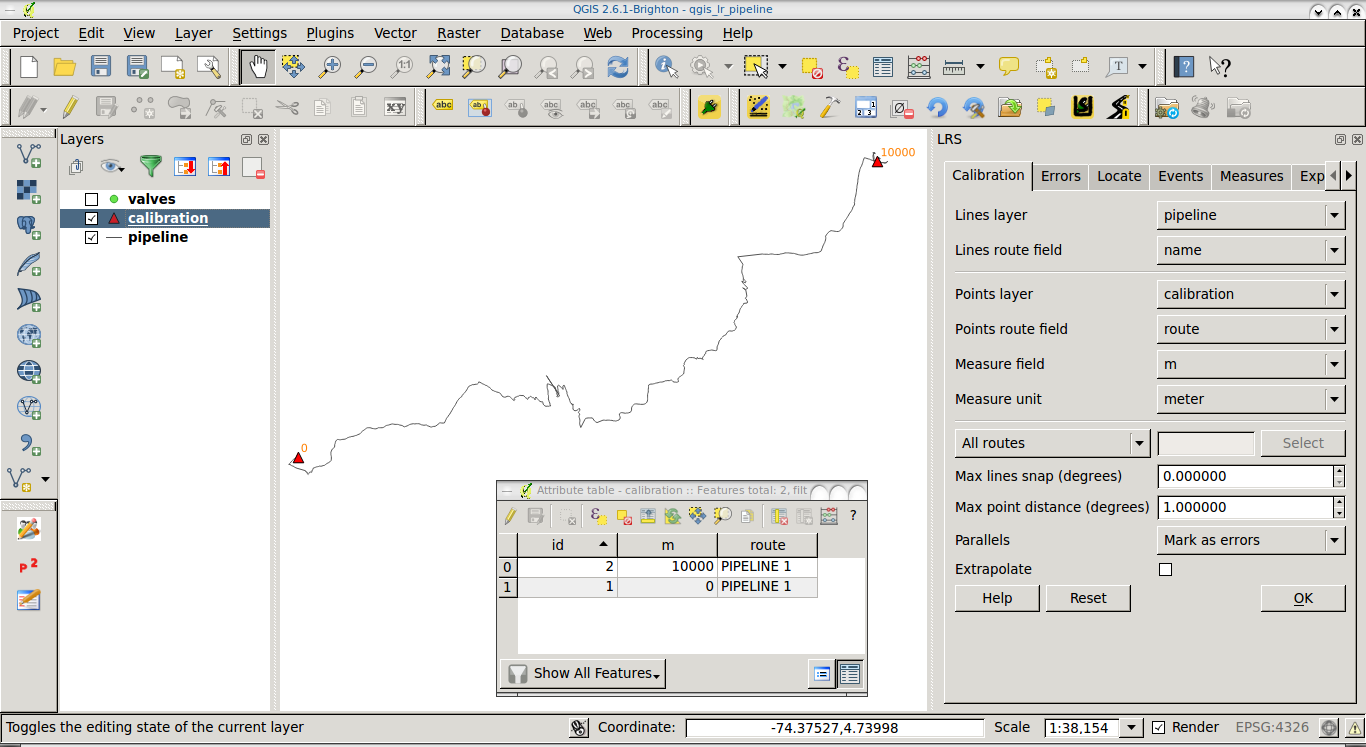
Based on both a line (routes) and a point (for calibration) layer, go to the Calibration tab.
- Select the line (pipeline) layer with its route field (a field that identifies routes, it's very useful if your line layer has several routes).
- Select the calibration point layer with its corresponding route (point route value should match with the line route value) and measure fields. As you can see, you would need a calibration point layer with at least two points, which could be located at the start and the end of the route, with values of 0 and 10000 in case that the route has 10km.

- Click on Ok to interpolate M values along the routes.
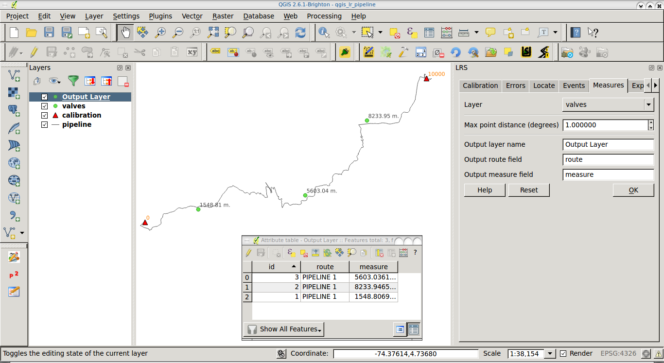
Go to the Measures tab.
- Select your valves layer.
- Fill the output fields (They'll be applied to a new layer, don't worry).
- Click on Ok to get a new (memory) layer which will contain the M value (chainage) of each valve.
Don't forget to save the layer you obtain from 2., since it's a memory (temporal) layer.
In the following screenshot you can see a sample pipeline, a couple of calibration points (orange triangles), and a couple of valves not lying on the pipeline (green points) with their calculated chainage (M value).

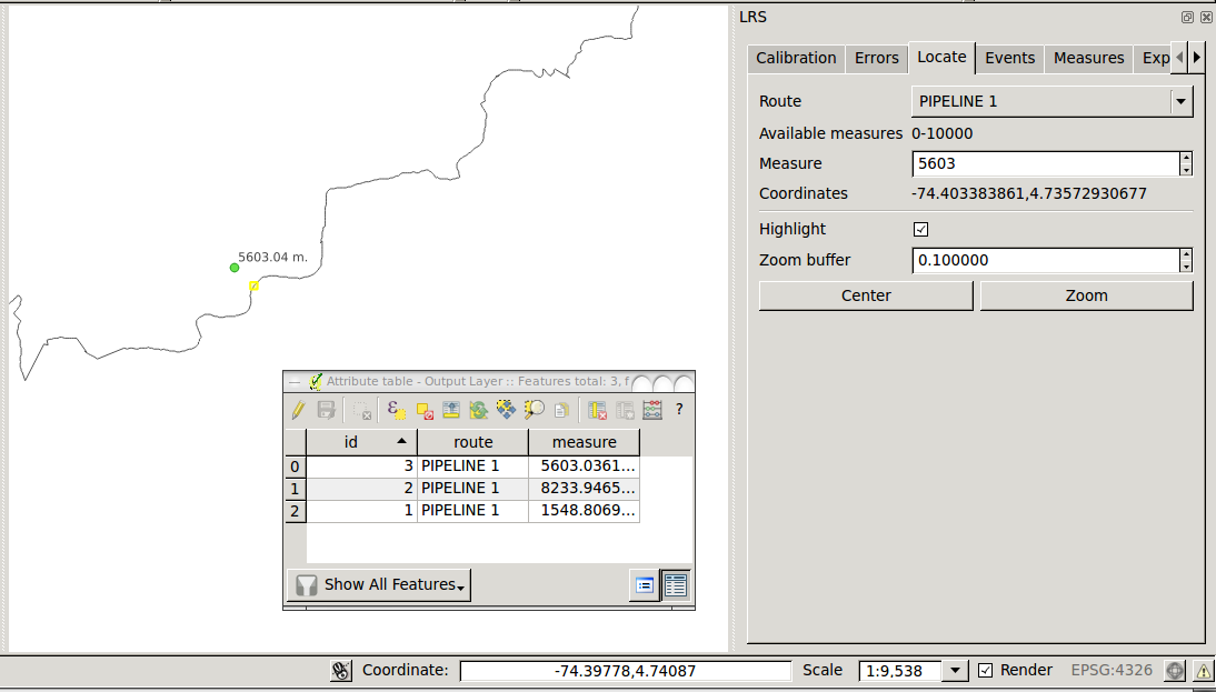
You can even verify the chainage of the valves by using the Locate tab. Just select your route and enter a known measure (e.g., 5603). You should see a yellow mark on the line, representing the projection of the valve on the line.

I use QGIS v.2.6.1. You can find documentation of LRS plugin here.


