16

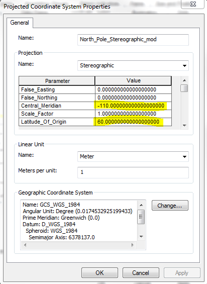
I'm currently working to import CANGRID climate data (provided as Surfer Grid ascii, ".grd" files) into ArcGIS. The grid is 95 rows by 125 columns in size.Metadata provides lat/lon of origin (lower left corner), cell size (50km) as well as notes projection as polar stereographic with central meridian (110 degrees W) and latitude of origin (60 degrees N).

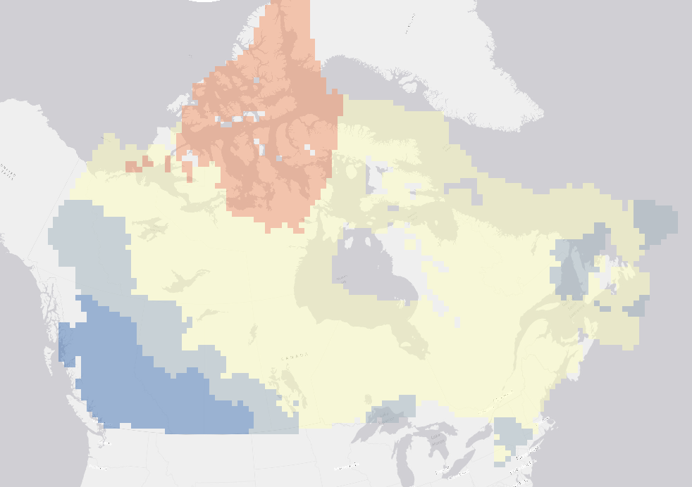
After first attempting to convert the .grd to rasters as .ascii and .flt unsuccessfully, I've managed to use GDAL to set the extent and projection, however the dataset does not correctly align with the boundaries of the intended area. See below image.
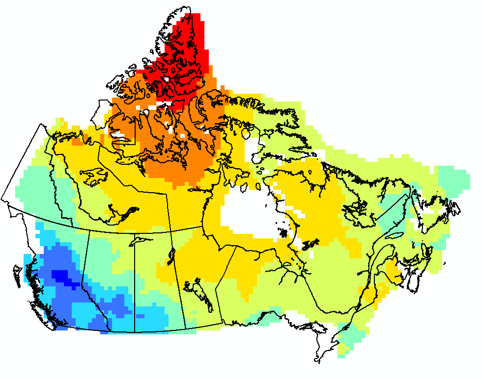
Is there an accepted geotransformation for polar stereographic that could explain this lack of alignment?

For instance, is there a specific conversion factor or rotation that I should be using?

An example file from the dataset is here: "t201113.grd"

Here's the code I am currently using in GDAL

ds = gdal.Open("t201113.grd")
array = ds.ReadAsArray()

x_rotation = 0
y_rotation = 0
xres = 1
yres = -1

llx = -129.8530
lly = 40.0451
ulx = -175.144
uly = 71.385

input_osr = osr.SpatialReference()
input_osr.ImportFromWkt(ds.GetProjection())

wgs84_osr = osr.SpatialReference()
wgs84_osr.ImportFromEPSG(4326)

wgs_to_nps_trans = osr.CoordinateTransformation(wgs84_osr, input_osr)
x, y, z = wgs_to_nps_trans.TransformPoint(llx,lly)

geo_transform = [ x, xres, x_rotation, y, y_rotation, yres ]

ncol = ds.RasterXSize
nrow = ds.RasterYSize

out_driver = gdal.GetDriverByName("HFA")
out_ds = out_driver.Create(t201113.img", ncol, nrow, 1, gdal.GDT_Float32)

out_ds.SetGeoTransform(geo_transform)

out_prj = 'PROJCS["North_Pole_Stereographic",GEOGCS["GCS_WGS_1984",DATUM["WGS_1984",SPHEROID["WGS_1984",6378137.0,298.257223563]],PRIMEM["Greenwich",0.0],UNIT["Degree",0.0174532925199433]],PROJECTION["Stereographic"],PARAMETER["False_Easting",0.0],PARAMETER["False_Northing",0.0],PARAMETER["Central_Meridian",-110.0],PARAMETER["Scale_Factor",1.0],PARAMETER["Latitude_Of_Origin",60.0],UNIT["50_Kilometers",50000.0]]'

out_ds.SetProjection(out_prj)

out_ds.GetRasterBand(1).WriteArray(array)
out_ds.GetRasterBand(1).SetNoDataValue(1.70141e+038)
out_ds.FlushCache()
out_ds = None
`

Also, here's the projection info, as defined by the input, i.e. from "GetProjection()":

'PROJCS["North_Pole_Stereographic",GEOGCS["GCS_WGS_1984",DATUM["WGS_1984",SPHEROID["WGS_1984",6378137.0,298.257223563]],PRIMEM["Greenwich",0.0],UNIT["Degree",0.0174532925199433]],PROJECTION["Stereographic"],PARAMETER["False_Easting",0.0],PARAMETER["False_Northing",0.0],PARAMETER["Central_Meridian",0.0],PARAMETER["Scale_Factor",1.0],PARAMETER["Latitude_Of_Origin",90.0],UNIT["50_Kilometers",50000.0]]'

And the input GeoTransform:

(-0.5, 1.0, 0.0, 94.5, 0.0, -1.0)

Lat, longs of the grid coordinates are also provided, and when view in the projected coordinate system look like below. When the geotransform is defined by coordinates of the lower left (yellow) or upper right (pink) cordinate, I can effectively set the extent, but there remains alignment issues throughout the raster.
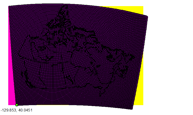
enter image description here

14
  • If you're using ArcGIS, switch to Stereographic North Pole and set the standard parallel to 60.0. The ArcGIS stereographic implementation uses a scale factor rather than a standard parallel because the proj can be centered anywhere.
    – mkennedy
    Commented Oct 3, 2014 at 19:52
  • Thanks @mkennedy - do you mean the "North Pole Stereographic" proj (WKID 102018)? I've set the latitude of origin and central meridian values using this projection and still have the same issue. Perhaps you are referring to another projection?
    – jsnider
    Commented Oct 3, 2014 at 20:33
  • No, you need one where the projection (method) is Stereographic_North_Pole. I don't think we have the exact PCS; try modifying from 3995 or 3413.
    – mkennedy
    Commented Oct 3, 2014 at 20:41
  • 1
    The metadata note that "The file grid_pnt_lls.txt lists the lat/longs for each x/y (0,0 = SW corner of grid)." With this file in hand you could reproject this grid to any coordinate system you want and go on from there.
    – whuber
    Commented Oct 9, 2014 at 21:02
  • 1
    Where can we download the vector layer to testing? Commented Oct 1, 2015 at 11:02

3 Answers 3

2

Too long for a comment, this is to accompany @Matej's answer.

  1. Add the “.grd” data into ArcGIS.
  2. Use the “Raster to Other Format” function and convert your .grd file into an ESRII GRID format. This is important because most of the raster functions in ArcGIS are accessible for this format only, either that or it usually gets too slow when you use it on other formats.

  3. As it already has the projection file associated to the file. Rather than projecting the new converted data, define its projection. ArcToolbox > Data Management Tools > Projections and Transformations > Define Projection. You can navigate to the pre-defined polar stereo graphic ESRII projection and see if its parameters match the one given in the metadata (it doesn’t), so you can modify it as per @Matej. Only here - rather than modifying, create a new one based on the NPS projection with the central meridian and Latitude of origin changed and save it on disk, then navigate to the new projection and use that when defining your projection. This is because your on the fly modification won't be available later on when you want to use it to set the coordinate system for your data frame, which is necessary in order to align your other boundary files to the same modified NPS system.

2

The proper projection information for these files can be found here: Define Proj4 string for CANGRD dataset

1
+100

I don't think you need to reproject the image. Only do the following:

  1. define(modify) the projection of the basemap
  2. georeference (shift) the image to the specified location

Note that the image (grd) is already in the North Pole StereoGraphic projection, which only gives you the indication of how to adjust the basemap that will be aligned with the image.

Step 1:

Modify the original North Pole Stereographic projection (WKID: 102018) to adjust the Latitude of Origin and Central Meridian:

enter image description here

Step 2:

Georeference the grd file by setting the lower-left corner to the specified coordinate (lat,lon). When you update georeferencing, the .gdwx file is created in the same folder. When assigning SW corner to (40.0451, -129.853) the content of the file looks as follows:

50000
0
0
-50000
-1730620.4315
2744092.9724

edit: the world file above has been manually modified based on the cell size and provided location of the SW corner - 5th and 6th line represent calculated location of the upper-left pixel of the image. The position of the image changed slightly.

The above values place (shift) the image to the specified location and define the scale.

And this is the output: enter image description here

If this doesn't seem to be aligned properly, I would question the provided coordinates for the SW corner of the image. In case you have access to the coordinates of i.e. the NE corner of the image, you can recalculate the transformation parameters that would scale and rotate the image between two (or more) points.

3
  • Is the .gdwx file a world file? If so, then the linked wiki article says lines 5 & 6 reference the upper left pixel. Are you suggesting setting it to the southwest (lower left) pixel? Commented Sep 29, 2015 at 20:23
  • No. I only specified the location of the SW corner as noted in the readme file. The structure of the file looks like the world file. It was generated using Georeferencing tool in ArcMap that may have calculated and stored the location of the NW corner - haven't checked yet.
    – Matej
    Commented Sep 29, 2015 at 20:27
  • 1
    Yes, I checked it now. The stored location in the .gdwx is the upper left corner.
    – Matej
    Commented Sep 29, 2015 at 20:44

Your Answer

By clicking “Post Your Answer”, you agree to our terms of service and acknowledge you have read our privacy policy.

Not the answer you're looking for? Browse other questions tagged or ask your own question.