Background:
ArcGIS Desktop 10.5.1, Spatial analyst
We have acquired two bare-earth DEMs derived from lidar. YEAR2007 was produced in 2007, and YEAR2015 eight years later. Both are 32-bit, floating-point tifs, with the same horizontal and vertical CRS/projection/datum and same pixel size (3 feet). YEAR2015 was snapped to YEAR2007.
We compared elevation values for both years at known control points on roads with open sky views. Both years matched the known values closely, within a mean difference of about 0.1 feet and standard deviation of about 0.3 feet.
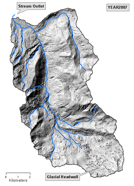
Here's a hillshade of the project watershed (northwest Washington state, USA) created from YEAR2007, with a few streams superimposed. Note that the ridges trend northerly. All appears normal. YEAR2015 looks similar:
The Problem:
We need to determine where stream channel deposition and erosion occurred between the two years by looking for increases or decreases in channel elevation, respectively. To accomplish this, we used the SA Minus tool, subtracting YEAR2007 from YEAR2015 (that is, YEAR2015 - YEAR2007).
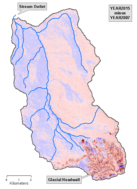
For the output "minus" tif, we assigned a blue color ramp to cells where elevation values increased between the two years, and a pink-red color ramp for decreased elevation values.
The output is displayed below. This is where the weirdness appears.
Although no hillshade is used in the following image, it has that impression because the blue and pink areas tend to follow the slope aspect(!) That is, easterly-facing slopes tend to contain increased elevation cells between the two years, and westerly-facing slopes tend to contain decreased elevation cells.
Using the Identify button, typical blue increases are around +2 feet, and pink decreases trend closer to -3 feet.
How is this possible? When compared at known control points, the two DEM elevation values match closely, as described above. But the difference output is, well, really different, with the odd pattern related to aspect.
Everyone here is scratching their head, and an internet search turns up nothing.
Certainly the earth has not heaved around according to aspect in the intervening eight years. Yet there certainly appears to be a relationship between aspect and DEM elevation differences!
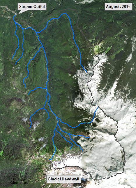
Here is a satellite image dated August, 2016:
After a great deal of testing, I did find the solution, which turned out to be quite simple.
The solution: shift one of the rasters (I chose YEAR2007) EXACTLY one cell to the EXACT northeast. Voila!, after subtracting the two rasters, the aspect effect disappeared completely - problem solved!
Although the two years' rasters were previously snapped and visually registered, this simple one-cell shift instantly and completely removed the aspect appearance. Based on the various helpful comments, I tested a lot of shifting in varying direction/distance combinations. Using the SA Shift tool, I shifted the YEAR2007 raster (recall, 3-foot cell size) each of the eight cardinal directions (north, northeast, east...) by the following distances (in feet):
0.01, 1.00, 3.00, 4.00, 6.00, 7.00, 7.50, 7.75, 8.00, 9.00
That's 80 different direction/distance combinations. After subtraction, the ONLY one that solved the problem was, as previously mentioned, to shift one of the two rasters exactly 3.00 feet - one cell - to the northeast (that is, 3.00 feet to the north and 3.00 feet to the east).
All 79 other combinations, following subtraction, resulted in some type of aspect effect.
(FWIW, given the 3-foot cell size, shifting at the 3.00, 6.00 and 9.00 distances retained the original snapping; all other values "undid" the snap)
With the problem solved, I was able to complete the project.
However, the original question remains unanswered: How does the elevation difference between the two (now known to be misaligned) years result in an ASPECT effect?
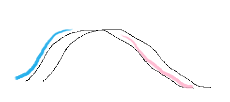
Perhaps re-framing the question would be of interest: Imagine that these two rasters had been correctly registered from the beginning, showing no aspect effect upon subtraction. Would we then expect to create an output aspect raster by 1) purposely mis-aligning them and then 2) subtracting them? Is that how the SA Aspect tool works?


