I have imported a DXF file (site layout drawings for proposed development), but its scaling is too small and it does not line up with the Google street maps. I want to re-scale the layer manually based a common feature on the aerial photo and correlating the length of the same feature on the dxf import. I then want to move the layer manually to line up with a particular point on the map.
5 Answers
I was a tester of the 3.0 version of QAD plugin, which I consider an impressive programming job.
The plugin is still in the experimental phase, but you can install it if you enable the option to install experimental plugins in QGIS.
If you install it, you will see that you can use CAD like commands with your QGIS layers. You will find the MOVE, ROTATE, SCALE, and ALIGN commands among others. Of course, you need to have a basic understanding of how these commands operate in a CAD system.
If you need help with the use of some of these commands, you can ask another question specific to their use.
Testers are welcome by the developer.
The Plugin AnotherDXFImporter contains a module for georeferencing:

3.2.1. Parameter
By means of X and Y offset, a simple displacement of the DXF can be achieved. This is y.B. useful when the original coordinates have been shortened in the CAD / system.
3.2.2. World files for CAD datasets
A world (.wld) file is a text file containing control points that describe a coordinate transformation. A world file can be used to extend the properties of a CAD drawing to include georeferencing information. The information is stored as coordinate values that define one or two displacement vectors called links.
The data comprises two or four pairs of coordinates organized into two rows. Each row defines a displacement link using the following syntax: . The first pair of coordinates in each row corresponds to the source coordinates, also known as the from-coordinates. These values represent the x,y location of any known control point in the CAD drawing. The second pair of coordinates in each row corresponds to the destination coordinates, also known as the to-coordinates. These values represent a new location in geographic space, typically a reference point in another feature layer. Source: arcgis.com
If the coordinate transformation is activated and the plug-in finds a corresponding WLD-file it is automatically integrated and the DXF file is transformed accordingly.
3.2.3. Transformation over 1-4 identical points
Similar to the CAD data set, a transformation takes place via identical points. The number of parameters for the transformation depends on the number of the given points. Note: An output of the residuals for over-determination is currently not.
You could try using a click and point vector georeferencing plugin like Vector Bender. I georeference all my imported dwgs with this. https://plugins.qgis.org/plugins/VectorBender/
You import your dwg/dxf as an editable format e.g. using Another DXF Importer or QGIS's own dwg/dxf->gpkg tool in QGIS 3.x (Projects tab), which will be in the wrong area/scale to begin with.
Then indicate two pairs of source and destination points (two lines on the canvas). This will shift, scale and rotate your data so it matches up to the points. You probably won't need a third line.
Note you may need to install later versions of some Python libraries for the plugin to work.
-
The latest supported version Vector Bender 0.2.1 only working for QGIS 3.0.0 (2.99 dev)– sys49152Commented Jun 27, 2021 at 10:56
I could not find a way to do this directly like in a drawing software. There are however two ways to do this:
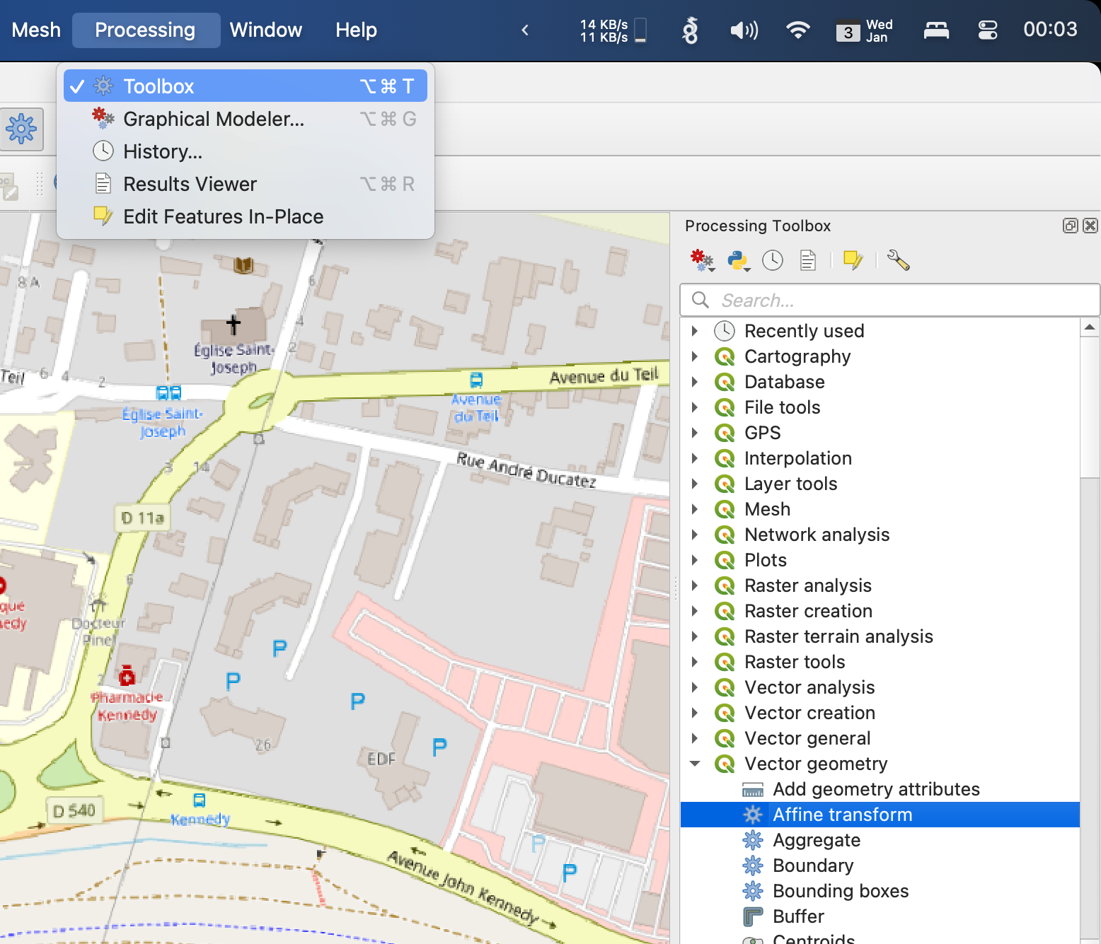
Use the Processing > Toolbox to apply many many basic operations to a vector layer. Look for "Affine transform" or simply "Translate". These work with manually entering the values for resizing, movement, rotation, etc.

Use the Layer > Georeferencer… to map key points in your shape to points on the main map. QGIS will use there to "mold" the shapes to the map so they match. This is more visual and satisfying, but still no Adobe Illustrator.
NOTE: If your file format is not directly recognized by Georeferencer, but it can be read by QGIS otherwise, just import first as a layer then export it to a shapefile.
To find Affine parameters use Layer > Georeferencer Then set point pairs and write world(wld) file. You could choose your aerial photo as input.
Read affine parameters from WLD for using in Processing > Toolbox > "Affine transform":
- Scale X is the 1st parameter in the world file.
- Scale Y is the 4th parameter
- Rotation X is the 3rd parameter
- Rotation Y is the 2nd parameter
- Translation X is the 5th parameter
- Translation Y is the 6th parameter

