16

Looking for an algorithm (python, formulas, whatever...) to georeference a single drone image based on its EXIF data.

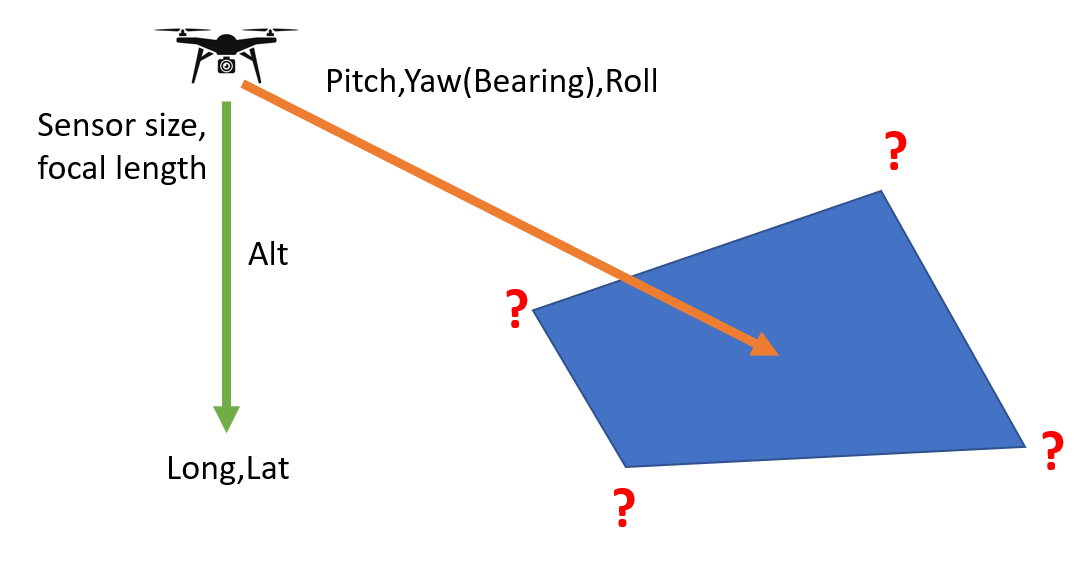
Specifically, I need to translate drone GPS latitude and longitude (after conversion to projected coordinates, of course), relative altitude, drone camera orientation (pitch, roll, yaw), and drone sensor parameters (sensor size and focal length) to ground coordinates of the centre and four corners of the drone image.

enter image description here

I'm comfortable assuming flat terrain, so this would be independent of the DEM, and recognize measured GPS coordinates will have imprecisions affecting the results too.

I'm aware that commercial UAV mapping software and services, such as Pix4D, DroneDeploy, and MapsMadeEasy.com, solve the much more complicated problem of stitching many such images together and extracting 3D terrain information, including dealing with those imprecisions. I'm looking to solve the much simpler problem of "what is this one image looking at, more or less".

Based on Getting coordinates of pixel from georeferenced drone photo?, I've also started looking at literature about "monophotogrammetry" and "monoplotting" (example: https://www.wsl.ch/en/services-and-products/software-websites-and-apps/monoplotting-tool.html), but the emphasis seems to be on interpolation of features/lines on the photo after manually identifying GCPs. In this context, I'm after the math to approximately but automatically identify the corners only.

I've dusted off my geometry and trigonometry knowledge, and can do simple cases with simple formulas. For instance, ignoring roll and yaw, the centre of the photo is (I think!) the following distance in front of the drone's GPS location, and likewise the horizontal field of view at the centre:

fwd_dist_img_ctr = altitude * tan(-pitch)
ground_fov_img_ctr = hypotenuse(altitude,fwd_dist_img_ctr) * sensor_width / focal_length

I'm hoping for leads how to extend this to a) the four corners of the image, and b) incorporating roll and yaw, and therefore camera direction (bearing) too.

Adding: seems this is embedded in GRASS' i.ortho.photo (https://grass.osgeo.org/grass78/manuals/i.ortho.photo.html), but buried behind a GUI focused on GCPs, correction, and stitching a map from multiple photos. I'm looking for the minimally complicated math to do it automatically, per single image.

Eventually, this will be used to visualize a layer of research drone photos on a map by the ground footprint displayed, rather than by GPS location of the drone/sensor itself. Probably as a processing algorithm in QGIS after extracting all of the pertinent EXIF tags as attributes.

6
  • You can certainly get a polygon shapefile showing the limits of an image in Agisoft. Here is a link to the python script that you use in Agisoft after adding and aligning images. Maybe that will help. github.com/ShuksanGeomatics/Agisoft_Tools/blob/master/…
    – GBG
    Commented Jan 19, 2021 at 16:40
  • @GBG, thanks. That's certainly heading in the right direction. However, the guts seem to be embedded in camera.transform.mulp(sensor.calibration.unproject(...)), which I'm guessing is a part of AgiSoft's proprietary API? Or do you know where to find that code by any chance? (I failed with a quick google search)
    – Houska
    Commented Jan 19, 2021 at 16:59
  • @GBG, thanks, will explore. BTW, one source of overestimation can be the following: many (most?) consumer drone cameras do an edge crop, i.e. don't use maximum sensor extent for the image. I'm guessing, but might be due to image post-processing to remove artifacts in their small-sensor images and wide-angle lenses. In any case, effective field of view is less than expected from physical sensor specs reported in some places. Could easily lead to an overestimate, esp. since it's the Wild West as far as what's put into different EXIF tags!
    – Houska
    Commented Jan 20, 2021 at 3:39
  • That edge crop issue is one reason we do calibration of orthos for wildlife survey using ground dimensioning markers, though we normally are only interested in average footprint of nadir images instead of pixel mapping.
    – Simbamangu
    Commented Feb 2, 2021 at 5:41
  • Hi @Houska did you ever develop a good solution to this? I'm working on exactly the same problem and have yet to find a clean workflow.
    – clifgray
    Commented Mar 4, 2021 at 19:50

1 Answer 1

7

As requested, posting my own (partial) answer. The actual math is not too bad, but there are surrounding issues making application difficult:

  1. UAV camera focal length specs seem to be before sensor cropping. In addition, there is post-processing to remove distortion. Therefore the published focal length, sensor size, and/or angular field of view specs need correction to accurately determine the image corners. (This is approximated with the ccf factor below, but is inaccurate in a way that varies between different cameras. Therefore, probably need to manually calibrate for each drone.)

  2. The simplification of assuming terrain is flat is (in my case, at least) sufficiently often violated that the projected image rectangle is not reliable. This is because not only is the assumption that terrain is flat over the image area, but also that its elevation is the same as the drone take-off point, since only then is the relative altitude correct.

With those limitations, here's the math in Python-like pseudo-code (I actually prototyped in Excel, and then gave up for the reasons above).

Example

# photo parameters, here with example data
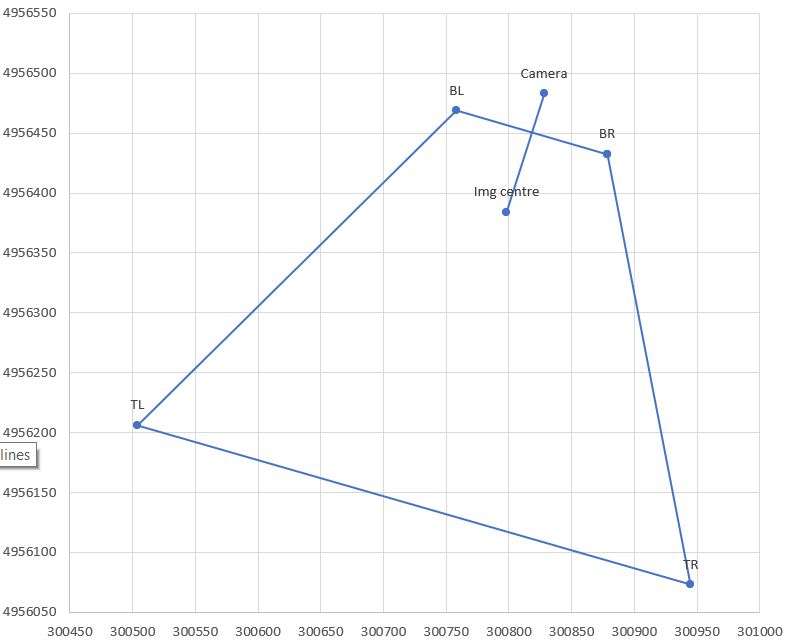
CamX,CamY = 300828, 4956483 # camera/drone GPS coordinates converted to a projected CRS
A = 95.1 # relative altitude, EXIF tag RelativeAltitude for DJI drones
pitch = -42.6/180*3.14159 # degrees from EXIF tag GimbalPitch converted to radians. Always negative.
dir = -163.2/180*3.14159 # camera azimuth (direction clockwise from N). EXIF tag FlightYawDegrees

# camera paramaters
Cf = 4.49 # camera focal length in mm. This is for DJI Mavic Mini.
SX = 6.3 # sensor width in mm
aspect = 0.75 # aspect ratio, usually 3:4 or 9:16
Sd = SX * sqrt(1+aspect^2) # sensor diagonal in mm. Should correspond to Cf, but usually doesn't, see ccf below

# calculations
ratXh = SX/Cf/2 # ratio of sensor half-width to focal length (at image centre)
ratYh = aspect * ratXh # ditto for sensor half-height
ccf = sqrt(1+ratYh^2) # "corner correction factor" due to sensor crop and fisheye correction. For 0.75 aspect this becomes 1.13, but needs to be calibrated for each camera!
phiXh,phiYh = atan(ratXh),atan(ratYh) # 1/2-FOV angle in X,Y directions at image centre. Will be in radians.

Kc,Kf,Kb = A/tan(-pitch+{0,1,-1}*phiYh) # ground distance of camera ground projection to image; centre, front, back
Rc,Rf,Rb = sqrt(A^2+{Kc,Kf,Kb}^2) # full distance, hypotenuse of ground distance and altitude triangle
Wch,Wfh,Wbh = {Rc,Rf,Rb} * ratXh / {1,ccf,ccf} # 1/2 width of frame in ground coordinates, at centre, front, back; includes ccf fudge factor in corners

# now express the projection centre and corners in K,W coordinate system, i.e. ignoring rotation in dir
Centre_W,_K = 0,Kc
BR_K = BL_K = Kf
TR_K = TL_K = Kb
BL_W = -BR_W = Wfh
TL_W = -TR_W = Wbh 

# finally rotate using dir
Centre_x,BR_x,BL_x,TR_x,TR_y = CamX + (corresponding _W) * cos(dir) + (corresponding_K) * sin(dir)
corresponding _y = CamY - (corresponding _W) * sin(dir) + (corresponding_K) * cos(dir)
4
  • Thank you for sharing the results of your work. I used it for an Android project and I'm interested in integrating a DEM to have a more correct projection of the image. Have you thought about it ?
    – dmjf08
    Commented Aug 19, 2021 at 8:08
  • I thought about it briefly, but ran out of steam/interest before thinking too much. Adjusting for terrain via a single point, whether the drone position or an approximation of the centre of the image, shouldn't be too hard. Reflecting the differences in the DEM across the image, e.g. if one corner is higher than another, would be a hassle.
    – Houska
    Commented Aug 19, 2021 at 14:38
  • @Houska could you please explain why did you choose FlightYawAngle from EXIF and not GimbalYawAngle. My understaining: the camera is mounted on gimbal and the gimbal yaw angle is independant from drone itself, it is positive angle clockwise varying from -180 to 180 degrees from North but which North, magnetic or geographic like the one used on maps, no idea.
    – Khaled
    Commented Aug 19, 2022 at 22:56
  • @Khaled, I’m traveling and don’t have my notes, but I believe I felt the same as you from the definitions but either my DJI Spark or Mavic Mini didn’t populate it or populated incorrectly. One of the frustrations is the lack of standardization of drone EXIF tags (as well as sensor diameter meaning etc). Will need to check live on your drone.
    – Houska
    Commented Aug 21, 2022 at 0:45

Not the answer you're looking for? Browse other questions tagged or ask your own question.