3

I have a layer of street segments that are within a given distance of a fire station. Now I want to make a border around these street segments. If I use Buffer, it puts a buffer around each segment. If I use Convex Hull it makes a border around the street segments but does not follow the street segments but rather cuts across them. What I really need is an outside buffer of the street segments that follows the outermost street segments.

Is it possible in QGIS?

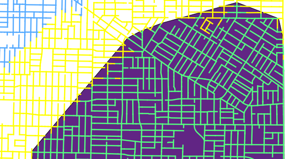
The image below shows the problem. The lines in green represent street segments that can be reached from a given point within 4 minutes. The yellow is 6 minutes and the blue is 8 minutes from the same point.

When I put a convex hull around the green segments (shown in purple), the hull includes some of the yellow segments because a convex hull is based on the smallest polygon that contains all of the lines. I see that a concave hull is what I really need, but QGIS does not support the concave hull.
enter image description here

0

2 Answers 2

2

There is a concave hull option in QGIS but it's available in the Processing toolbox only; it only works on points, so you have to extract nodes before you run it.

  1. Extract nodes;
  2. Open Processing toolbox and select Concave Hull from the QGIS geoalgorithms;
  3. Choose the point layer from (1), and select a threshold - '1' is just like a convex hull, and the smaller the number the more concave the result (experiment!).

This can be done more easily using a model, without the need to save intermediate sets of nodes:

  1. Open the Processing toolbox and select Models|Tools|Create new model.
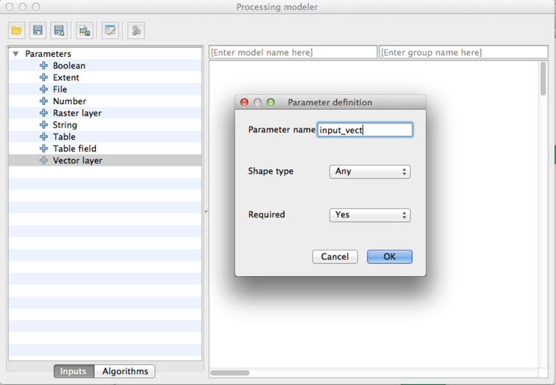
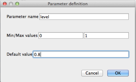
  2. Add two parameters (drag from parameters list on left) - one will be the input vector (any type of vector - point, polygon, line) and the other (drag a 'Number' parameter across) will be the threshold as per the 'Concave hull' dialog:

enter image description here

enter image description here

  1. Switch from the Parameters tab to the Algorithms tab in the modelbuilder, find the 'Extract nodes' and drag that into the model. The input vector should automatically be indicated as the input layer; click 'ok'.
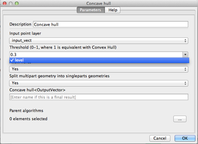
  2. Find and drag in the Concave hull algorithm. Change three options:
    • The "Input point layer" should be "Output layer from algorithm 'Extract Nodes'";
    • The threshold should be the number parameter you gave a name to in 3 - 'level' in my example below;
    • Give the output a name in the last text box, i.e. concave_hull.

enter image description here

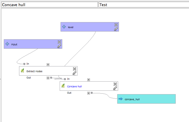
  1. The graphical model should now look something like this:

enter image description here

  1. Enter a group name (i.e. 'Test') and a model name ('concave hull'), then save the model in the default location.

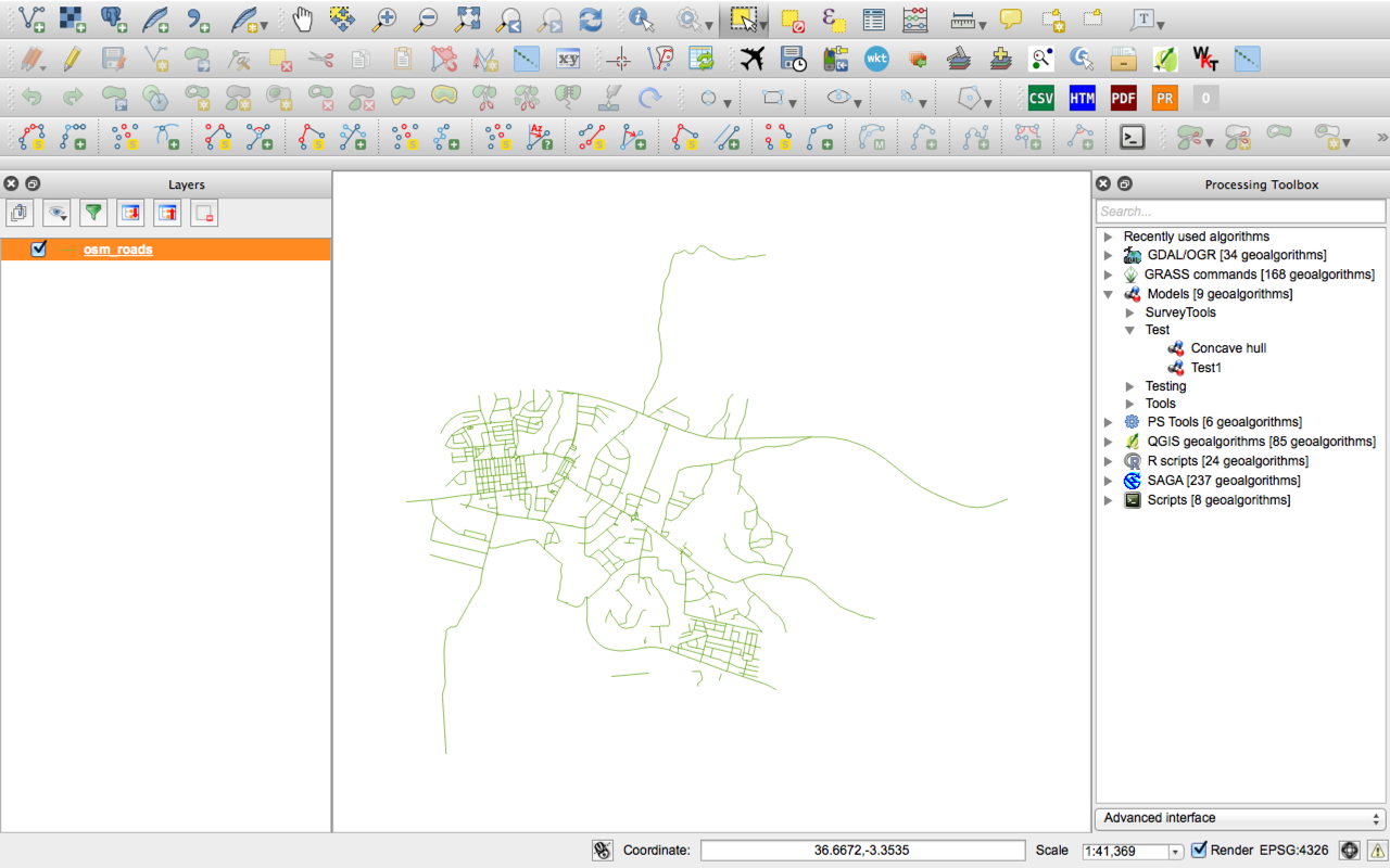
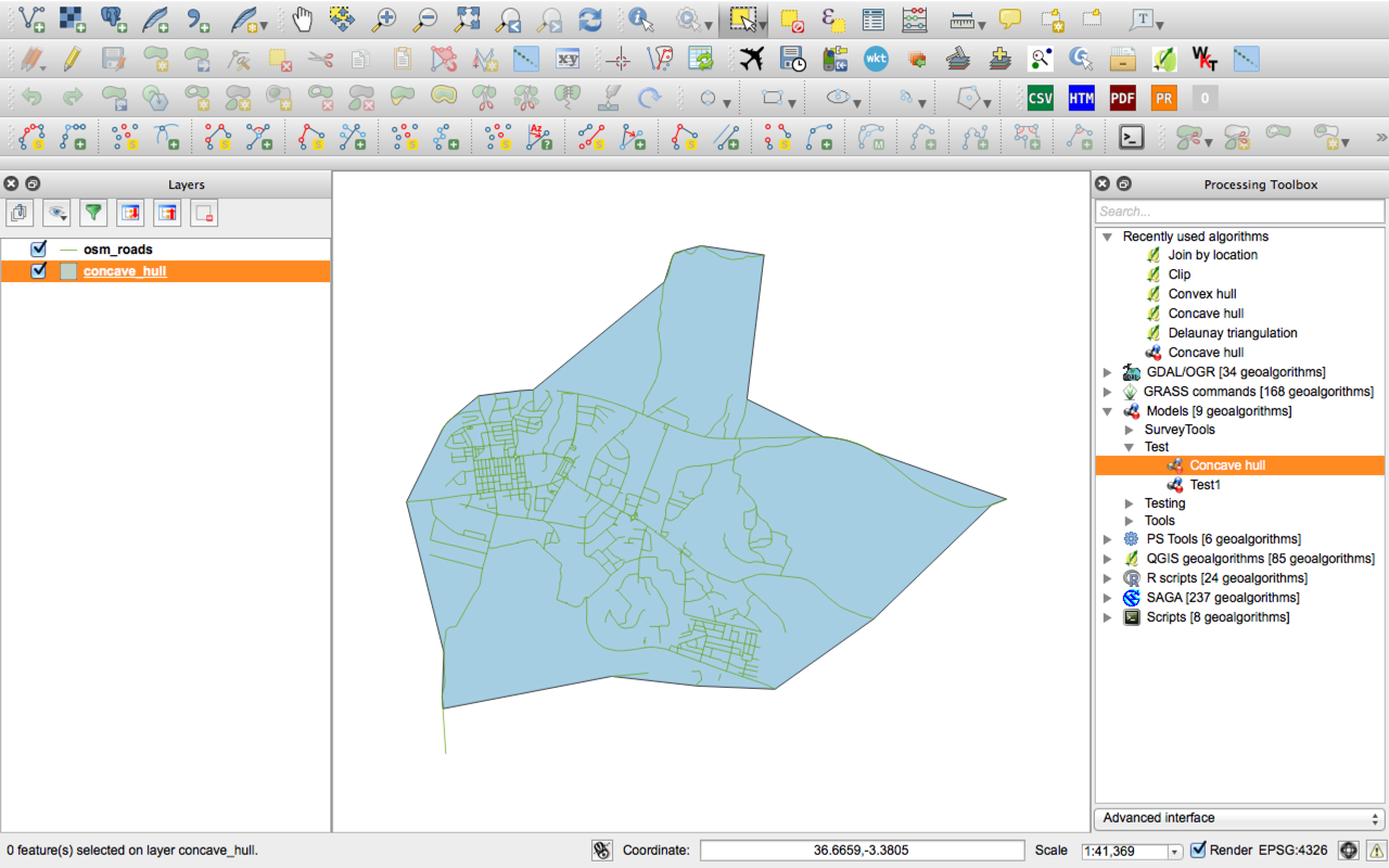
To run, add a set of points, lines or polygons, then double-click the model and run it on your layer:

enter image description here

enter image description here

1

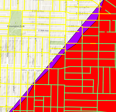
The PostGIS answer seems to be the best Open Source solution. I do not have PostGIS available to me at work, however. I wound up using FME's HullAccumulator tool. The screenshot shows the concave hull in red over the convex hull in purple.

enter image description here

There are still a few yellow lines within the concave hull, but it is much better than the convex hull.

0

Your Answer

By clicking “Post Your Answer”, you agree to our terms of service and acknowledge you have read our privacy policy.

Not the answer you're looking for? Browse other questions tagged or ask your own question.