7

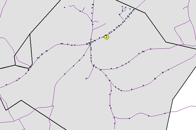
I have a road network (purple), Point files (green) and a beginning point (yellow).

I want to trace the point files based on the road network. Think of the points as telephone poles, but what I want is a map showing telephone lines (line shapefile). There is a numbering scheme for the "telephone poles" but it isn't great and for this instance I would just as well assume they are not numbered.

Does anyone have a solution? One that looks pretty good is just buffering the points and then clipping the road network from the buffers. But I want something more complete. It needs to be automated since there are 12,000 of the "telephone poles"

enter image description here

4
  • 1
    How would the solution you seek differ from, say, simply selecting the road features that are sufficiently close to any point? What precisely do you mean by "more complete"?
    – whuber
    Commented Nov 29, 2011 at 19:25
  • Well the road segment may extend pass the point 1000 feet. I used complete because when I clipped from buffers the network was choppy. What I should have said was more accurate.
    – Thad
    Commented Nov 29, 2011 at 19:33
  • 1
    You're right, you don't want to clip from buffers! It sounds like you want somehow to retract the road segments on which the poles might lie so that those segments don't extend too far beyond the runs of the poles. But how would you distinguish a gap along a long run from two distinct runs? Can you provide a criterion for this?
    – whuber
    Commented Nov 29, 2011 at 19:37
  • Well the gap's i don't think will be an issue. The black lines represent mini-service areas that are internal to the area. Well the reason, aside from just having it for visualization, is for planning, and possibly eventually adding more information within the line files than could be (useable) stored within the point files (ex. diameter).
    – Thad
    Commented Nov 29, 2011 at 20:04

4 Answers 4

9

There are many ways to deal with this, but a few stand out as being general and effective. To understand this, let's enumerate a few of the problems that might have to be dealt with:

  • There could be gaps between poles that are so great, the algorithm might view the gaps as being actual breaks in the transmission system.

  • There may be some short segments of road, crucial for connecting the roads into a network, that nevertheless do not have any poles near them. These segments would not be selected by proximity to poles but are a necessary part of the solution.

  • There may be poles not accessible by road from the central point. These poles might be parts of other transmission networks originating from other central points.

I am also adopting the stance that since you already have a polyline network (the roads), it would be advantageous to exploit it rather than connecting the pole points with a completely new polyline, which is likely not to parallel the roads very well.

These considerations suggest that the ingredients of a good solution would include a few key steps:

  1. Compute the road distances from the central point to all poles.

  2. Identify the poles that have locally maximum distances along their particular road segment: that is, none of their neighbors along the same segment have greater distances.

  3. Form the shortest paths back from these local maxima to the central point.

The union of these shortest paths would trace out the transmission network. (Indeed, step 2 is not really necessary, but it would greatly reduce the computation involved in step 3.)

Steps 1 and 3 can be carried out using a network representation (in Network Analyst) or a raster representation (in Spatial Analyst, using a CostDistance or FlowAccumulation calculation). Step 2 is a straightforward database summary: after step 1, each pole will have its road segment and distance as attributes. Find the maximum distance by road segment and select the poles attaining those maximum distances.

There are some potential problem situations:

  1. Some poles might not be close to roads. There's nothing in the problem statement that tells us what should be done about these. They can be handled automatically with raster calculations (an appropriate cost grid will assign high impedances to non-road cells, but not infinite impedances, allowing isolated poles to become connected to the nearest roads, but not to each other, unfortunately). At the least, after obtaining the solution in step 3 you can select all poles not on that network and consider how they should be handled (perhaps by manually creating connections for them or maybe with a Euclidean minimum spanning tree solution).

  2. If some road segments form loops, you should skip step 2, for otherwise portions of those loops may be lost.

  3. The road polylines might not actually form a connected network. There can be tiny gaps between road segments (sometimes just millimeters in size) that split up a network that appears visually connected. This is a data quality problem that would plague any solution, except for some of the raster-based ones.


At one point I mentioned FlowAccumulation in passing. This may surprise people: what does this problem have to do with streams and watersheds? Stare at the image for a while. Imagine the origin point as the low point on a landscape and the roads with telephone poles as traces of streams flowing toward that low point. If we can create a surface for which the roads really are the streams, then we can let a little "rain" fall at the location of each pole and flow downhill. The points that get wet are the solution we seek: they connect the poles efficiently into a network that follows the roads. An appropriate CostDistance calculation--with low nonzero impedance along the roads and extremely high but not infinite impedance off the roads--will create exactly that kind of surface. Another way to create that surface is from the Euclidean distance grid for the roads. That's perfect, except the roads are level. They have to get tilted; for this, add an extremely small multiple of the distances along the roads to the Euclidean distance grid. (The road distance still requires a CostDistance calculation, which is expensive, but this time it only needs to be carried out for road cells, rather than all grid cells, which will speed it up by orders of magnitude. That permits us to use an extremely high-resolution grid if we like, thereby avoiding possible discretization errors made with coarse grids.)
7

Basically following whuber's approach, I would try this:

  1. Split the road at the (yellow) starting point.
  2. Add three fields to the roads: FROMDIST, TODIST and PARENTROAD_ID. FROMDIST will store the distance from the starting point for the from node of the polyline, likewise for TODIST. PARENTROAD_ID will store the ROAD_ID of the road that is closer to the starting point.
  3. Build a Minimum Spanning Tree composed of road sections, then compute FROMDIST, TODIST and PARENTROAD_ID values accordingly.
  4. Add three fields to the points featureclass: ROAD_ID, DISTANCE, and PARENTPOINT_ID.
  5. For each point, find the closest road feature, then interpolate a DISTANCE value based on a the FROMDIST and TODIST of the polyline along with the distance along the polyline computed via ICurve.QueryPointandDistance.
  6. For each point, calculate the PARENTPOINT_ID, representing the ID of the next point closer to the starting point.
  7. For each point create a linesegment between itself and the point referenced by PARENTPOINT_ID. Write this polyline to an output featureclass.
3

It sounds to me like you really are looking for a Geometric Network in a geodatabase.

What if you created a geometric network where your roads would serve as your "trunk lines" and then simply add "feeder lines" that run perpendicular from your roads to your points. Then you should be able to "set and view flow direction, change analysis settings, add flags and barriers to analyses, and perform various trace tasks." (see section called "Utility Network Analyst toolbar"). Also see "About tracing on geometric networks" for more detail on other types of analysis you can do with a geometric network.

This would require a little setup, but by creating an automation process of connecting the points to the network, it should be fairly quick and easy to update as new points are added to the network.

NOTE: "Although geometric networks can be both created and edited in ArcInfo and ArcEditor, they are read-only in ArcView". (From "Building a geometric network from existing simple feature classes")

1

As a starter (not the complete solution).
We probably need to know data format, version and license level of your arcgis.

What I see is to utilize the road network as a linear referencing system, and then "re-number" the poles in the correct sequence.
Then you should be able to use one of several tools (I'm sure someone else's answer will define that more clearly) to create polylines from the poles.
Here is the arcgis 10 tutorial for linear referencing

1
  • Data format - shapefiles? have arcinfo 10. Also have network analyst, but only on arc9.3 (trial version). Interesting I will read about linear referencing.
    – Thad
    Commented Nov 29, 2011 at 19:16

Your Answer

By clicking “Post Your Answer”, you agree to our terms of service and acknowledge you have read our privacy policy.

Not the answer you're looking for? Browse other questions tagged or ask your own question.