0

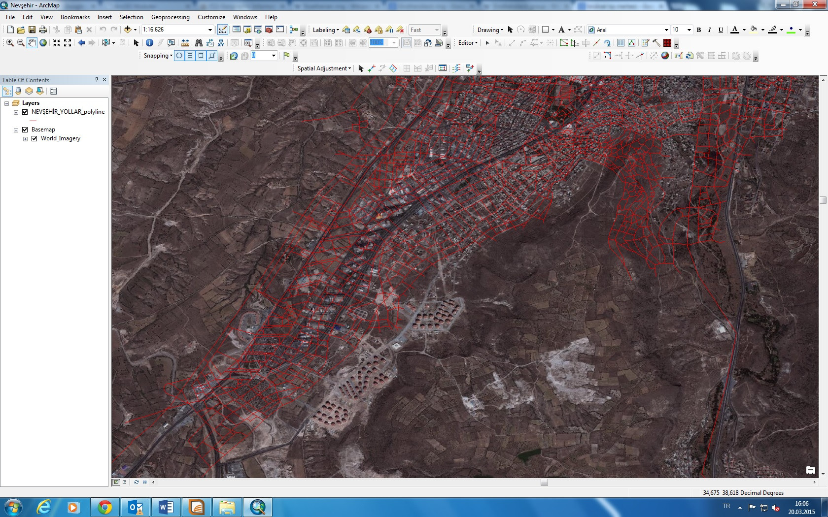
I have a satellite image and CAD data of the same area. The polylines from CAD to not overlay correctly on the satellite image. I want to fix polylines to their true coordinates but I could not fix them.

I'm trying spatial adjustment but they did not place truly. Is there anything I can do to correct this problem, or could my CAD drawing be wrong?

In Spatial Adjustment, which adjustment type should I use ?

  • Affine
  • Projective
  • Similarity
  • Rubbersheet
  • Edge snap

enter image description here

1 Answer 1

4

You should take into mind two main notions:

  1. Spatial adjustment is a complex and multistep process. You should find reliable anchors to which you should adjust the vector layer. On a raster, such as a basemap, such a process can be much more complex since of raster resolution and accuracy problems, in paticular when using a base map. Don't hesitate to use more than one steps in order to adjust your vector data, to its place.
  2. My second, and more important point, is that you should double check if you are indeed needed to adjust your vector data. That is since basemap is using a WGS84 web mercator as a coordinate system. That alone might distort its location - see EPSG 3857 or 4326 for GoogleMaps, OpenStreetMap and Leaflet and Measuring distances and areas when your map uses the Mercator projection; Furthermore, adding a basemap changes the data frame (on-the-fly; display) coordinate system to the basemap cooridnate system - and as a result, it distort any data which hasn't got the same spatial refrence. Thus check if your vector data coordinate system is WGS 1984 Web Mercator, unless it is you should change the date frame coordinate system, see this page from ESRI for detailed instruction of how to do it.
0

Your Answer

By clicking “Post Your Answer”, you agree to our terms of service and acknowledge you have read our privacy policy.

Not the answer you're looking for? Browse other questions tagged or ask your own question.