I am trying to adjust a shapefile using ogr2ogr spline transformation with cmd commands like:
C:\OSGeo4W64\bin\ogr2ogr.exe -f "ESRI Shapefile" C:\path\output.shp -tps --optfile C:\path\gcp.txt C:\path\input.shp
I have more than 1000 control points (so they are in a separate file). And I have strange problems with precision of this method. I already saw in this question that ogr2org spline method is not really exact. But with my number of GCP and the extent of my dataset I see that the precision dramatically decreases from north to south. Like this:

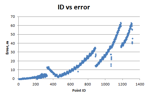
In the north the method is almost exact (0.001 m error), then it smoothly loses the precision and in the south it creates an error about 60 m.
I calculated RMSE for every GCP and plotted it versus coordinates and the ID number of control point (I was creating the GCP starting mostly from north). And I have:
I tried to find and read the source code of gdal (I found gdal_tps, thinplatespline and ogr2ogr_lib modules) but I don't know that language (C++?) and don't understand how the method works. Polynomials 1, 2 and 3 order of ogr2ogr are working fine (they are not exact methods but the error is not progressing).
So, why spline precision logarithmically decreases depending on the Y coordinate? (For X coordinate I see jumps in precision every 16000 m). How is this possible? How this adjustment method works? How can I solve this problem? (I have Windows 7, 64 bit)


